Method And Device For Drying A Flow Of Biomass Particles

a biomass particle and flow technology, applied in the direction of electrically static cleaning, cleaning processes and apparatus, lighting and heating apparatus, etc., can solve the problems of limiting the efficiency of the drying process, less available to both the drying gaseous medium and the approach is very costly, and achieves the reduction of drying time and power consumption of the dryer, and the effect of enhancing heat and moisture exchang

Inactive Publication Date: 2009-01-08
FORCE TECH +1
View PDF16 Cites 15 Cited by
  • Summary
  • Abstract
  • Description
  • Claims
  • Application Information

AI Technical Summary

Benefits of technology

[0029]It is a further object to provide a method and system enabling efficient drying of a flow of biomass particles using a gaseous drying medium.
[0038]In this way, the large amount of energy typically present in such systems is utilized in generating ultrasound with a high effect and sound pressure level. Further, since the gaseous drying medium is present in traditional systems already less modifications are needed for modifying traditional system into applying the present invention.

Problems solved by technology

However, independently of the type of dryer and thermal conditions in relation hereto, a basic condition will always command and limit the efficiency of the drying process: namely the energy and mass (moisture) exchange at the surface of the biomass particles (i.e. heat in, moisture out).
The fibres, usually transported in an airborne flow while drying and application of binder, tend to lump together and thus become less available to both the drying gaseous medium and the application of binder.
In terms of energy consumption this approach is very costly and in terms of singularising the fibres it is not very efficient.
Furthermore transporting the fibres in an airborne flow while drying does not guarantee an efficient process even in a high velocity, turbulent airflow.
The fibres follow the air flow with approximately the same velocity and only a very low air velocity is obtained at the surface of the fibres and, consequently, the exchange of energy and moisture (heat energy in, water vapour out) at the surface of the fibres is very inefficient.
All above disadvantages of the traditional process apply to the MDF manufacturing process.
The ultrasound sound pressure and drying capacity of JP 7055339 A has due to the specific arrangement a maximum effect that does not make it suitable for drying an airborne flow of wet biomass particles.
The application of a freezing agent hinders the efficiency of the drying process as (heat)energy is removed from the process due to the presence of the freezing agent.

Method used


Image

  • Method And Device For Drying A Flow Of Biomass Particles
  • Method And Device For Drying A Flow Of Biomass Particles
  • Method And Device For Drying A Flow Of Biomass Particles

Examples


Embodiment Construction

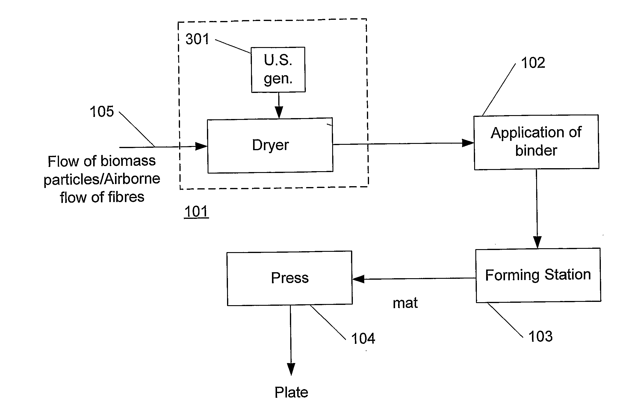
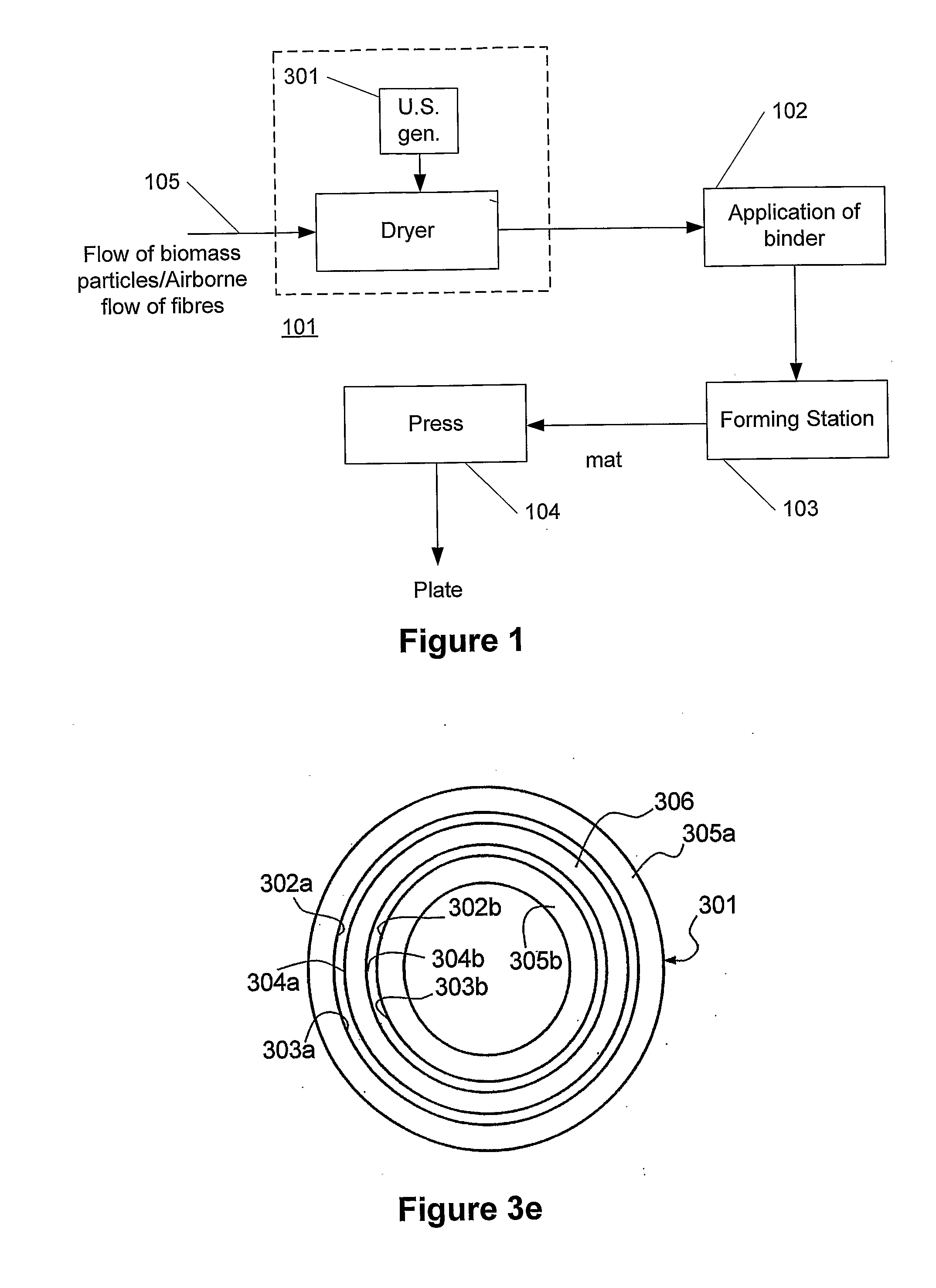
[0068]FIG. 1 schematically illustrates a block diagram of one embodiment of a system / method of the present invention. Illustrated is a dry fibreboard production line, i.e. a process of manufacturing plates such as MDF (Medium Density Fibreboards) or the like, where a synthetic binder is applied to biomass particles such as wood fibres or the like.

[0069]The process preferably involves an airborne flow of fibres (105) that is fed into a dryer (101) according to the present invention that dries the fibres to a moisture content of 1-20% or preferably 1-10% of dry matter, as explained in greater detail in the following.

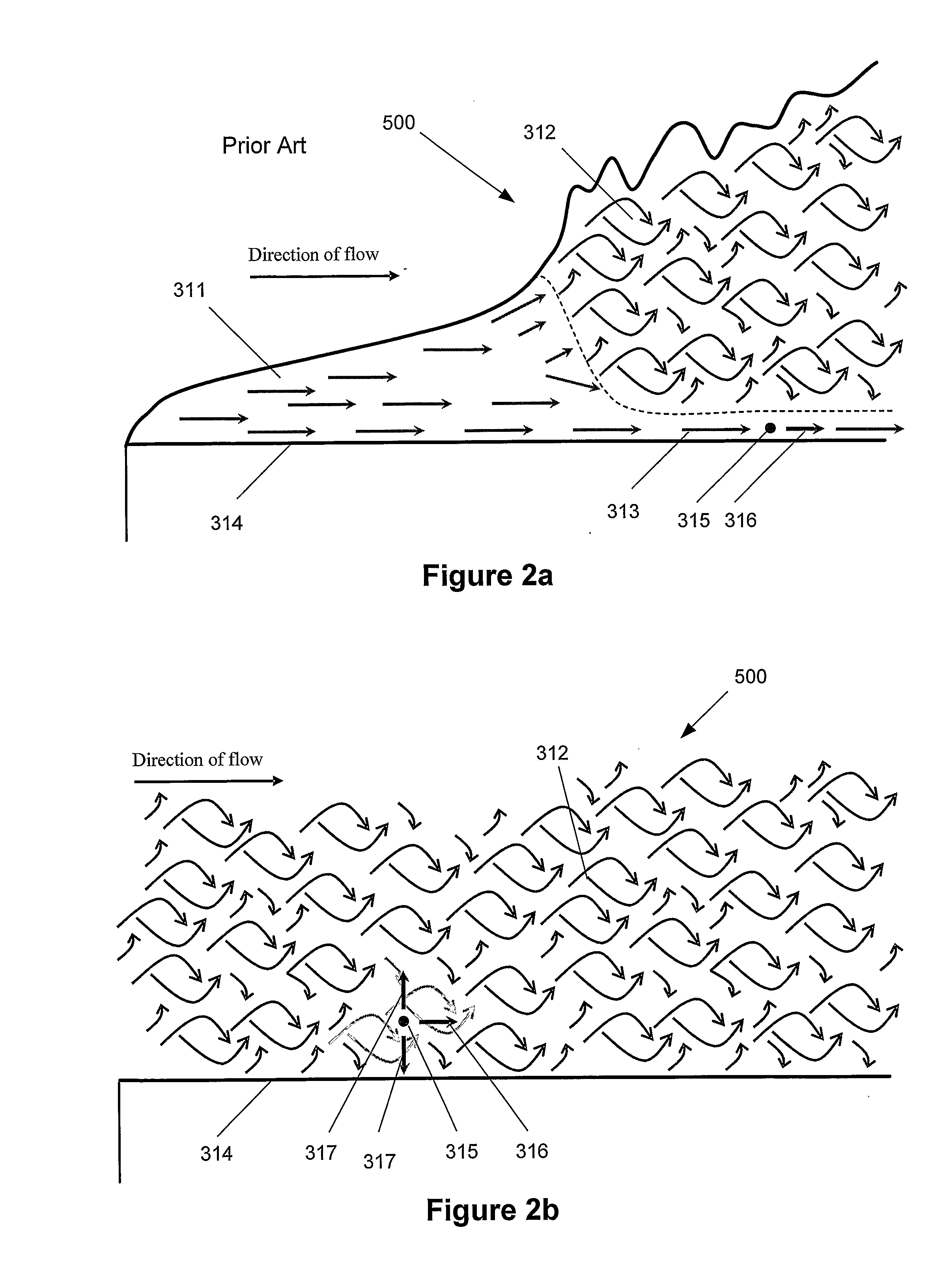
[0070]According to the present invention, the dryer (101) comprises one or more ultrasound generators (301). In this way, a more efficient drying of the fibres is obtained, which result in a significant acceleration of the drying process. The reason is that the ultrasound minimizes or eliminates the laminar sub-layer, as described below, where the absence of the sub-layer ...


PUM


Abstract

A method and a system to be used in the process of manufacturing plates, such as fibreboards, particleboards and the like boards, where the raw material in the form of biomass particles, such as wood fibres or wood particles of various size and shape are dried from its natural moisture content to a moisture content suitable to be applied with a thermosetting binder and be spread onto a movable forming belt to form a mat, and where said mat by means of a hot press is compressed into the desired thickness of the finished plate and the thermosetting binder is hardened. According to the invention, the drying process of the biomass particles is facilitated by the use of ultrasound to remove the sub-layer of air at the surface of the particles and thus to intensify the transport of heat energy into the particles and the transport of moisture from the particles.

Description

FIELD OF THE INVENTION[0001]The invention relates to a system for drying a flow of biomass particles. The invention further relates to a method of drying a flow of biomass particles.BACKGROUND OF THE INVENTION[0002]In traditional manufacturing of biomass-based plates, panels or boards, in the wood industry usually called particleboards, MDF-boards (Medium Density Fibreboards) and OSB (Oriented Strand Boards), the raw material in the shape of wood or biomass particles, fibres or larger particles (strands) are dried from its natural moisture content, usually in the range of 80-120% of water in relation to dry matter of material, to a moisture content suitable for the subsequent process of application of binder, forming and hot pressing, in a convection drying process using a flow of hot air or hot steam to apply heat energy to the material and to remove the evaporated moisture in the form of water vapour from the surface of the material.[0003]The efficiency of the process of drying wo...

Claims


Application Information

Patent Timeline
Patent Type & Authority Applications(United States)
IPC IPC(8): F26B5/02F26B3/04F26B17/00
CPCF26B17/10F26B5/02
Inventor KREBS, NIELSDUEHOLM, STEN
Owner FORCE TECH
Why Eureka
Try Eureka