Wire with excellent suitability for drawing and process for producing the same

a technology of wire and drawing, applied in the field of wire rods, can solve the problems of difficult wire drawing, and achieve the effect of suppressing breakage and reducing the content of hydrogen

Active Publication Date: 2009-01-08
KOBE STEEL LTD
View PDF3 Cites 14 Cited by
  • Summary
  • Abstract
  • Description
  • Claims
  • Application Information

AI Technical Summary

Benefits of technology

[0009]A manufacturing method according to an embodiment of the invention is positioned as a useful method for manufacturing the hot-rolled wire rod having the described property, that is, excellent wire drawability. A first aspect of the manufacturing method of the embodiment of the invention includes: performing heating in which a billet satisfying requirement of the composition (except for the hydrogen content) is held at 500 to 730° C. for 60 min; heating the billet to 950 to 1250° C., and performing hot rolling of the billet to make a wire rod at rolling temperature (Tr) of 800° C. or more and finish rolling temperature (Tf) of 1150° C. or less; placing the hot-rolled wire rod on a cooling bed at coiling temperature (TL) of 1020° C. or less; and cooling the wire at an average cooling rate (CR2) of 5° C. / sec or less from the coiling temperature (TL) to 500° C.
[0013]Furthermore, an embodiment of the invention provides a method of reducing the content of hydrogen in steel, including heating in which a billet is held at 500 to 730° C. for 60 min or more, the hydrogen having adverse effect on wire drawability.
[0014]The inventors found that each of the contents of C, Si, Mn, Cr, P, S, N, Al and O in steel was specified, and the content of hydrogen in steel was decreased, and hardness was controlled to be in a certain range or lower, thereby the hot-rolled wire rod excelling in wire drawability was able to be provided, in which breakage was suppressed even in heavy work using wire rods having large diameters.

Problems solved by technology

However, the wire rod having the large wire diameter exhibits large work hardening due to heavy wire drawing, and furthermore as initial wire diameter is increased, the wire drawing becomes more difficult.

Method used


Image

  • Wire with excellent suitability for drawing and process for producing the same
  • Wire with excellent suitability for drawing and process for producing the same

Examples


embodiment

[0090]Hereinafter, while the invention will be described more specifically with an embodiment, the invention is not limited by the following embodiment, and it can be obviously practiced by being appropriately modified within a scope adaptable to the purport described before and after, and any of such modifications may be covered within a technical scope of the invention.

[0091][Manufacturing of Wire Rods]

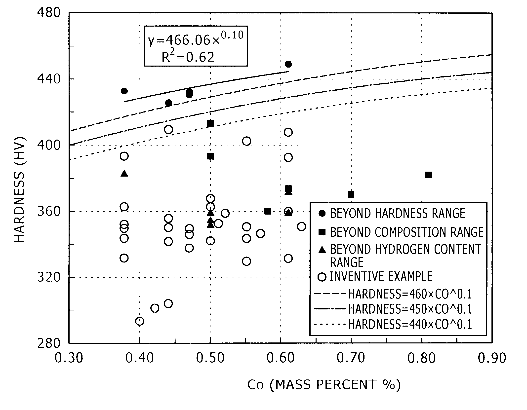
[0092]Steel materials having chemical compositions listed in Tables 1-1 to 1-2 (the remnant: iron and inevitable impurities) were ingoted, and shaped into billets 155 mm square. Next, soaking, heating, hot rolling, coiling, and cooling were performed in order under conditions listed in Tables 2-1 to 2-3, and consequently, hot-rolled wire rods 8.0 to 18 mm in wire diameter were manufactured.

TABLE 1-1Mass percentSteel type No.CSiMnCrPSNAlOA10.381.780.201.050.0080.0080.00410.03000.0019A20.402.090.851.830.0030.0020.00320.03210.0018A30.422.710.941.920.0020.0020.00280.00030.0010A40.441.92...


PUM

PropertyMeasurementUnit
grain diameteraaaaaaaaaa
temperatureaaaaaaaaaa

Abstract

A hot-rolled wire rod excelling in wire drawability is provided, in which breakage can be suppressed even in heavy work from a large diameter. A hot-rolled wire rod contains C: 0.35 to 0.65% (percent by mass, hereinafter expressed as well), Si: 1.4 to 3.0%, Mn: 0.10 to 1.0%, Cr: 0.1 to 2.0%, P: 0.025% or less (exclusive of 0%), S: 0.025% or less (exclusive of 0%), N: 0.006% or less (exclusive of 0%), Al: 0.1% or less (exclusive of 0%), and O: 0.0030% or less (exclusive of 0%), with the remnant consisting of Fe and inevitable impurities; wherein the content of hydrogen in steel is 2.50 ppm (ppm by mass, hereinafter expressed as well) or less, and hardness (HV) is 460×C00.1 or less (C0 indicates the content of C (percent by mass) in a position of depth of D / 4 (D: diameter of the wire rod)).

Description

TECHNICAL FIELD[0001]The present invention relates to wire rods that can be used for materials of wire-drawing products such as steel cords, bead wire, PC steel wire, and spring steel, and a method of manufacturing the wire rods; and particularly relates to hot-rolled wire rods excelling in wire drawability, in which breakage can be suppressed even in heavy wire drawing of wire rods having large diameters, and a manufacturing method of the wire rods.BACKGROUND ART[0002]In the wire rods or the spring steel for wire drawing, wire drawability has been improved by controlling microstructural factors, suppressing segregation, or the like. For example, JP-A-11-199977 proposes that pearlite nodule size, a center segregation level, and a lamellar interval of a pearlite structure are controlled in order to improve wire drawability (particularly, rod drawability) of wire rods. JP-A-2000-239797 proposes that mechanical properties of spring steel are appropriately adjusted to improve rod drawab...

Claims


Application Information

Patent Timeline
Patent Type & Authority Applications(United States)
IPC IPC(8): C21D9/52C22C38/34C22C38/20C22C38/22C22C38/32
CPCB21B1/16B21B3/00C21D3/06C21D8/065C21D9/525C22C38/50C22C38/04C22C38/20C22C38/28C22C38/34C22C38/42C22C38/002
Inventor KOCHI, TAKUYAMURAKAMI, SHOGOMIYAZAKI, SHOJIISHIDA, KENTOYAMA, MASAOKOIZUMI, FUJIO
Owner KOBE STEEL LTD
Why Eureka
Try Eureka