Plasma processing apparatus

a processing apparatus and plasma technology, applied in the direction of electrical apparatus, basic electric elements, electric discharge tubes, etc., can solve the problems of reducing the mechanical strength of the film, the metal surface of the barrier wall member is likely to be sputtered by the ions, and the film is deposited on the wafer. achieve the effect of high reliability

Inactive Publication Date: 2009-01-08
TOKYO ELECTRON LTD
View PDF8 Cites 34 Cited by
  • Summary
  • Abstract
  • Description
  • Claims
  • Application Information

AI Technical Summary

Benefits of technology

[0025]According to the present invention, hydrogen radicals generated from plasma formed in the plasma generation chamber can be selectively supplied into the processing chamber by blocking ultraviolet light and hydrogen ions also generated from the plasma and the hydrogen ions can be captured with a high level of reliability while ensuring that scattered metal atoms and scattered pieces of the material constituting the plate members do not enter the processing chamber.

Problems solved by technology

If the ultraviolet light is transmitted through the through holes and is directly radiated over the surface of the wafer, films deposited upon the wafer may become damaged and accordingly, the wafer needs to be shielded from the ultraviolet light.
In addition, the low-k film will be rendered more hydrophilic and the water content in the film will increase to result in a decrease in the mechanical strength of the film.
Under these circumstances, the metal surface of the barrier wall member is likely to become sputtered by the ions.
The barrier wall member, constituted with two plate members with through holes formed therein with an offset relative to each other in order to block ultraviolet light as described above, is particularly problematic.
As described above, there is a concern with regard to the barrier wall member constituted with a plurality of plate members formed by using a metal such as aluminum in that a greater number of metal atoms will scatter into space as the barrier wall member is sputtered by ions, resulting in a significant quantity of particles settling onto the wafer and serious metal contamination.
However, the level of force with which ions are attracted to a single shield plate constituted of an insulating material instead of a grounded metal is bound to be low, and ions will be allowed to pass through the through holes at the shield plate to reach the wafer and damage the film formed on the wafer.
However, ultraviolet light generated from the plasma will still travel through the through holes with a smaller diameter and the ultraviolet light having reached the wafer may damage the film on the wafer.
In addition, the presence of even a single metal mesh sheet in the shield plate is likely to induce metal contamination inside the processing chamber.(patent reference literature 1) Japanese Laid Open Patent Publication No. 2006-073722(patent reference literature 2) Japanese Laid Open Patent Publication No. 2002-083803(patent reference literature 3) Japanese Laid Open Patent Publication No.

Method used


Image

  • Plasma processing apparatus
  • Plasma processing apparatus
  • Plasma processing apparatus

Examples


Embodiment Construction

[0037]The following is a detailed explanation of the preferred embodiment of the present invention, given in reference to the attached drawings. It is to be noted that in the description and the drawings, the same reference numerals are assigned to components having substantially identical functions and structural features to preclude the necessity for a repeated explanation thereof.

(Structural Example for the Plasma Processing Apparatus)

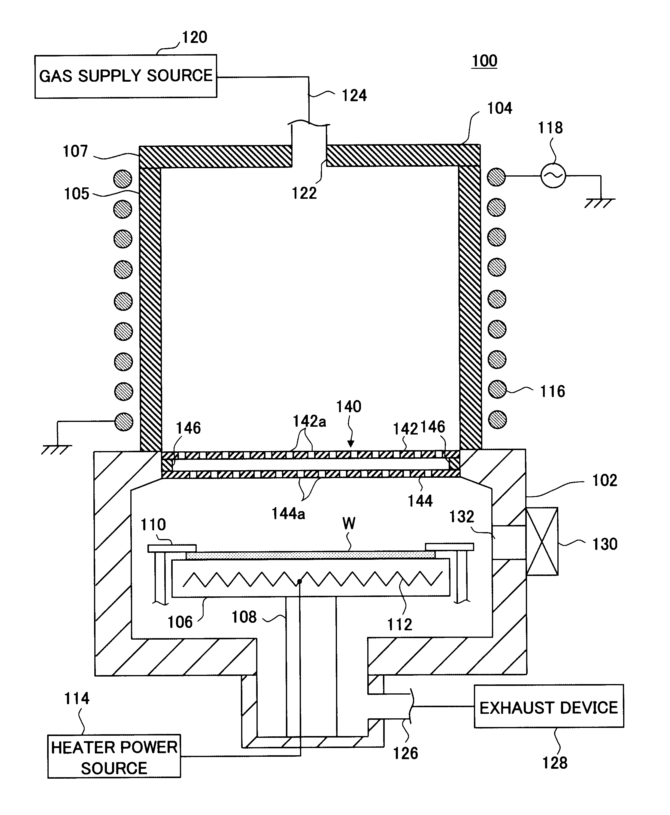
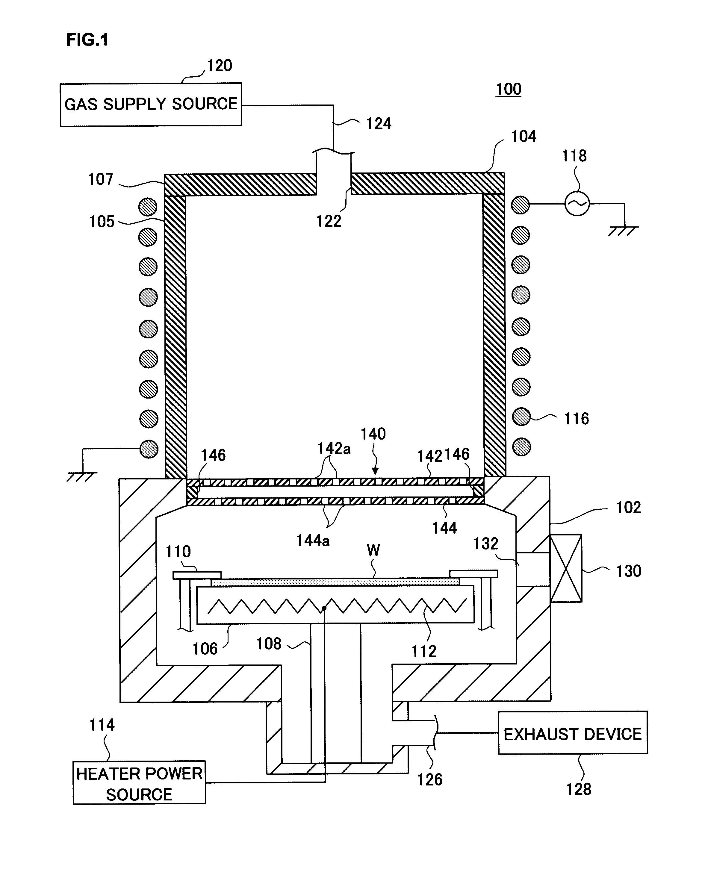
[0038]First, in reference to a drawing, a structural example that may be adopted in the plasma processing apparatus achieved in an embodiment of the present invention is explained. The following explanation is provided by assuming that the present invention is adopted in a down-flow type plasma processing apparatus that processes substrates by using hydrogen radicals generated from plasma (hereafter may be referred to as “hydrogen plasma”) raised from a hydrogen-containing processing gas. FIG. 1 is a longitudinal sectional view schematically illustr...


PUM

PropertyMeasurementUnit
frequencyaaaaaaaaaa
frequencyaaaaaaaaaa
temperatureaaaaaaaaaa

Abstract

A plasma generation chamber and a processing chamber are isolated from each other by a barrier wall member disposed between them. The barrier wall member includes two plate members and stacked one on top of the other over a gap, a plurality of through holes and, via which hydrogen radicals are allowed to pass, are respectively formed at the plate member and the plate member. The through holes at one plate member are formed with an offset relative to the through holes formed at the other plate member and the plate members are both constituted of an insulating material that does not transmit ultraviolet light.

Description

CROSS-REFERENCE TO RELATED APPLICATIONS[0001]This document claims priority to Japanese Patent Application Number 2007-174447, filed on Jul. 2, 2007 and U.S. Provisional Application No. 60 / 973,786, filed on Sep. 20, 2007, the entire content of which are hereby incorporated by reference.FIELD OF THE INVENTION[0002]The present invention relates to a plasma processing apparatus that executes a specific type of processing on a processing target substrate with hydrogen radicals generated by exciting a processing gas containing hydrogen to plasma.BACKGROUND OF THE INVENTION[0003]During a manufacturing process for manufacturing, for instance, semiconductor devices, a specific film formed on a processing target substrate such as a semiconductor wafer (hereafter may be simply referred to as a “wafer”) is selectively etched and removed by using a resist film formed at the surface of the wafer as a mask and then the resist film is removed through ashing. During the ashing process, oxygen radica...

Claims


Application Information

Patent Timeline
Patent Type & Authority Applications(United States)
IPC IPC(8): H01L21/306
CPCH01J37/321H01J37/32633H01J37/32357
Inventor TAHARA, SHIGERUNISHIMURA, EIICHIYAMAZAKI, KUMIKO
Owner TOKYO ELECTRON LTD
Why Eureka
Try Eureka