Hydraulic Energy Storage with an Internal Element

Inactive Publication Date: 2009-01-08
HALL DAVID R MR
View PDF17 Cites 43 Cited by
  • Summary
  • Abstract
  • Description
  • Claims
  • Application Information

AI Technical Summary

Benefits of technology

[0009]The at least one compressible element may comprise a grooved surface. The at least one compressible element may comprise a material selected from the group consisting of composite material, Kevlar, polyurethane, polyethylene, Twaron, aramid fiber, nylon, rubber, carbon, synthetic polymers, chloroprene, elastomers, polyester, carbon fib

Problems solved by technology

The hydraulic fluid m

Method used


Image

  • Hydraulic Energy Storage with an Internal Element
  • Hydraulic Energy Storage with an Internal Element
  • Hydraulic Energy Storage with an Internal Element

Examples


Embodiment Construction

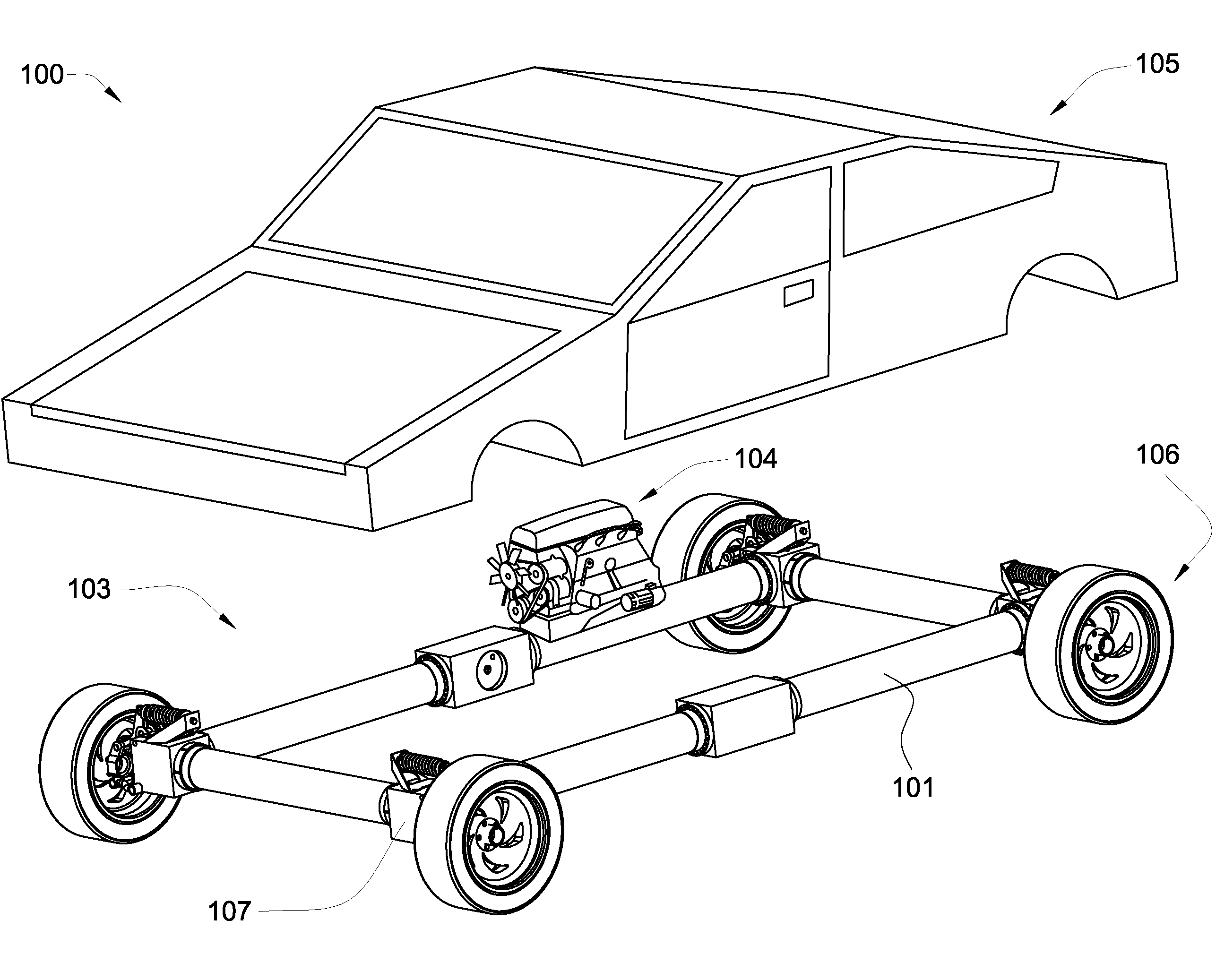
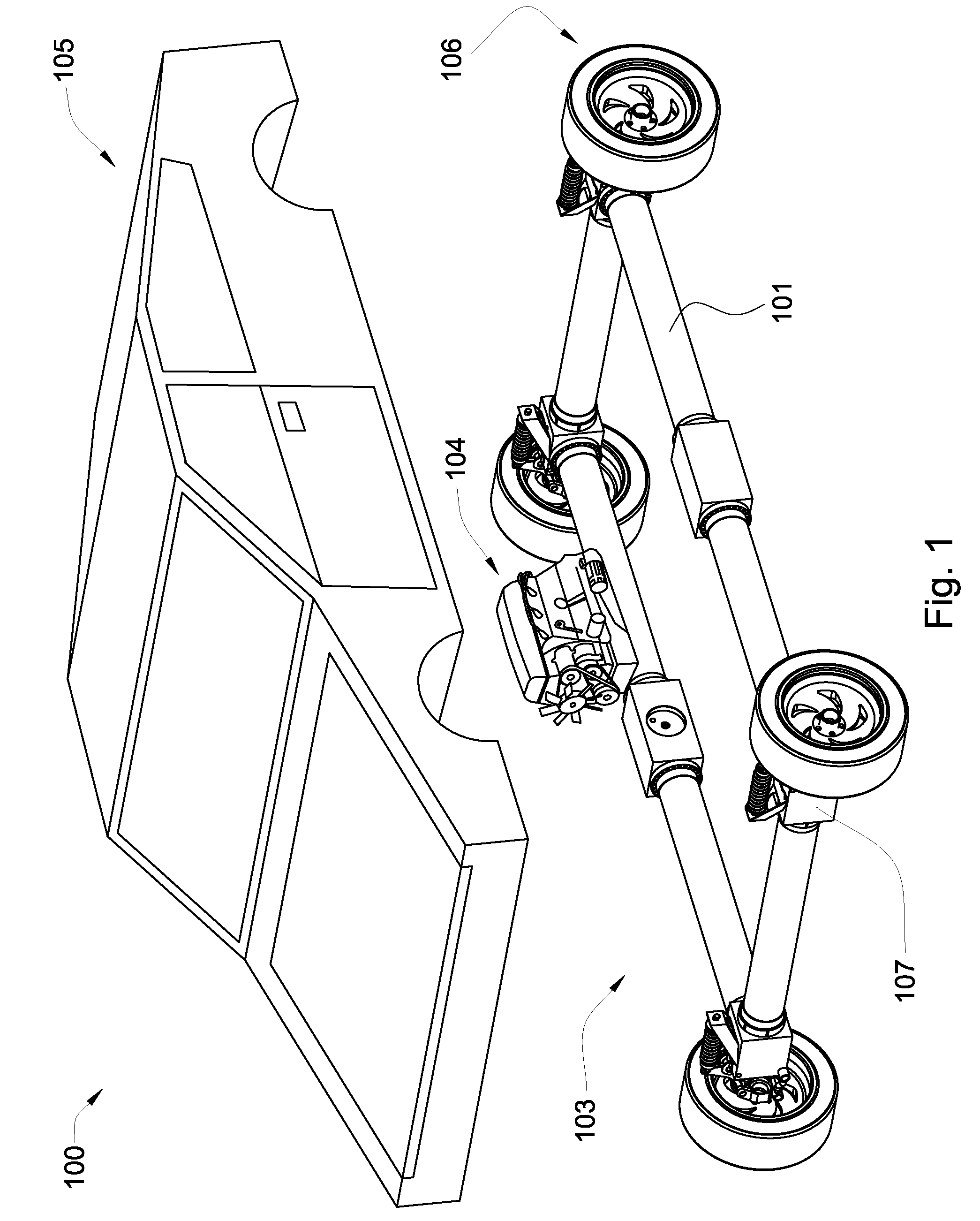
[0030]The current invention may be incorporated into a vehicle 100 such as an automobile, as in the embodiment of FIG. 1. A plurality of hose segments 101 may be incorporated into the system 103, connected by a plurality of manifolds 107. The manifolds 107 may be proximate translation assemblies 106 or an engine 104. The engine 104 may power the pressurizing mechanism 1003. The translation assemblies 106 may be in mechanical communication with individual hydraulic actuators disposed within the manifolds 107.

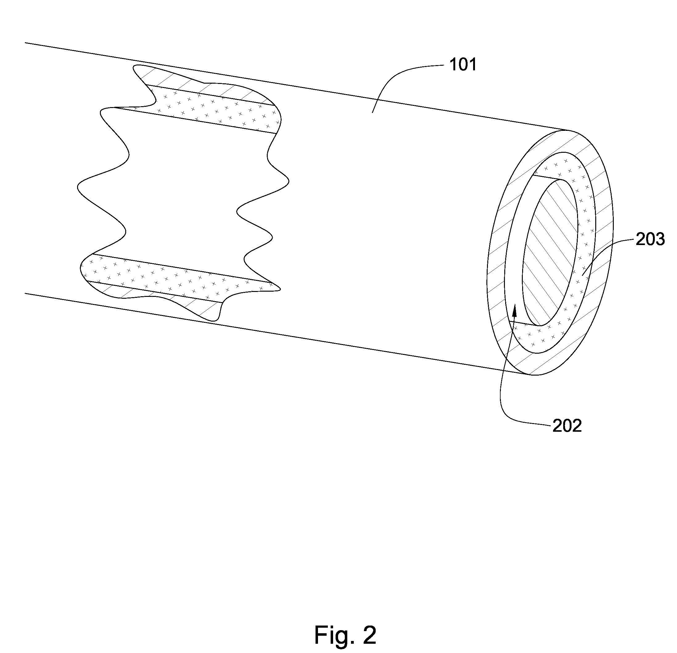
[0031]Referring now to FIG. 2, the hose segments 101 may comprise a material selected from the group consisting of composite material, Kevlar, polyurethane, polyethylene, Twaron, aramid fiber, nylon, rubber, carbon, synthetic polymers, chloroprene, elastomers, polyester, silicone rubber, rubber foam, carbon fiber, glass fiber, aluminum, copper, titanium, steel or a combination thereof.

[0032]A internal element 202 is disposed within the hose 101 and may comprise at least 40 percen...


PUM


Abstract

In one aspect of the present invention, a system for performing work having a hydraulic circuit comprising a length of hose a hydraulic fluid in the circuit in communication with the hose, a hydraulic actuator for doing the work, at least one compressible element disposed within the hose, and a mechanism for pressurizing the hydraulic circuit such that at least 50 foot pounds of energy is stored within the hose to perform the work.

Description

CROSS REFERENCE TO RELATED APPLICATIONS[0001]This application is a continuation-in-part of U.S. patent application Ser. No. 11 / 829,732 which was filed on Jul. 26, 2007 and entitled Expandable Vehicle Frame. U.S. patent application Ser. No. 11 / 829,732 is a continuation-in-part of U.S. patent application Ser. No. 11 / 773,561 which was filed on Jul. 5, 2007 and entitled Energy Storage in an Elastic Vessel. U.S. patent application Ser. No. 11 / 773,561 is a continuation-in-part of U.S. patent application Ser. No. 11 / 772,334 which was filed on Jul. 2, 2007 and entitled Energy Storage. This application is inhere incorporated by reference for all that is discloses.BACKGROUND OF THE INVENTION[0002]The current invention relates to hydraulic systems for performing work. Hydraulic systems are used in many different applications such as automobiles, trucks, construction equipment, elevators, submarines, and many others. Hydraulic systems may be used to improve such areas as fuel efficiency and pow...

Claims


Application Information

Patent Timeline
IPC IPC(8): B60K6/00
CPCB60K6/12B60K6/52B62D21/16Y02T10/6265B63H21/20Y02T10/6208B62D21/17E02F9/2217Y02T10/62
Inventor HALL, DAVID R.WAHLQUIST, DAVIDLEANY, FRANCIS
Owner HALL DAVID R MR
Why Eureka
Try Eureka