
Device for detecting infrared radiation with bolometric detectors

a technology of infrared radiation and detector, which is applied in the field of devices for detecting infrared radiation, can solve the problems of small relative variation in electrical resistance, adversely affecting signal quality, blind bolometers, like imaging bolometers, and certain functions of the read circuit, and affect the noise phenomena of the read circui

Inactive Publication Date: 2009-01-08
ULIS SAS
View PDF17 Cites 12 Cited by
  • Summary
  • Abstract
  • Description
  • Claims
  • Application Information

AI Technical Summary

Benefits of technology

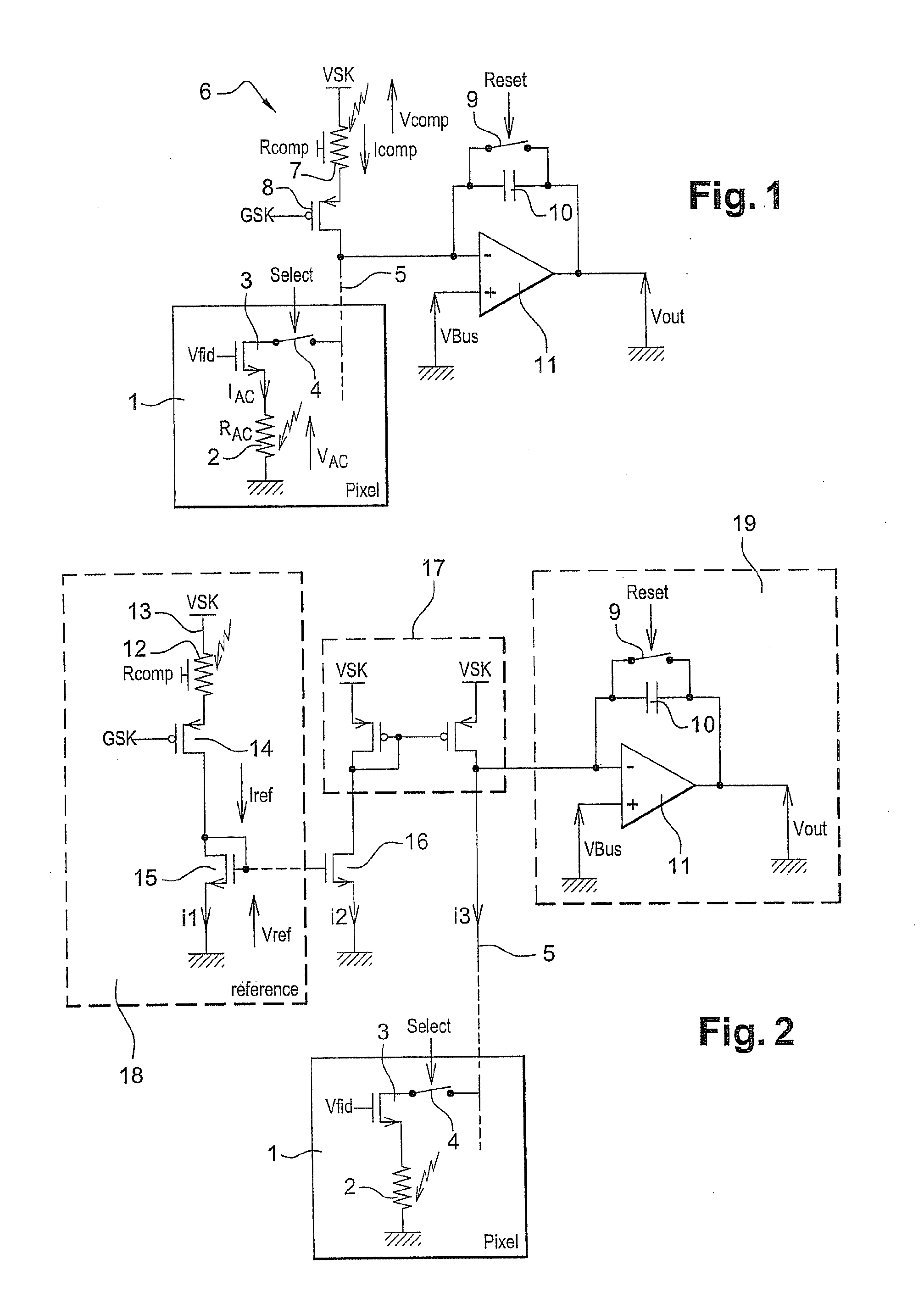
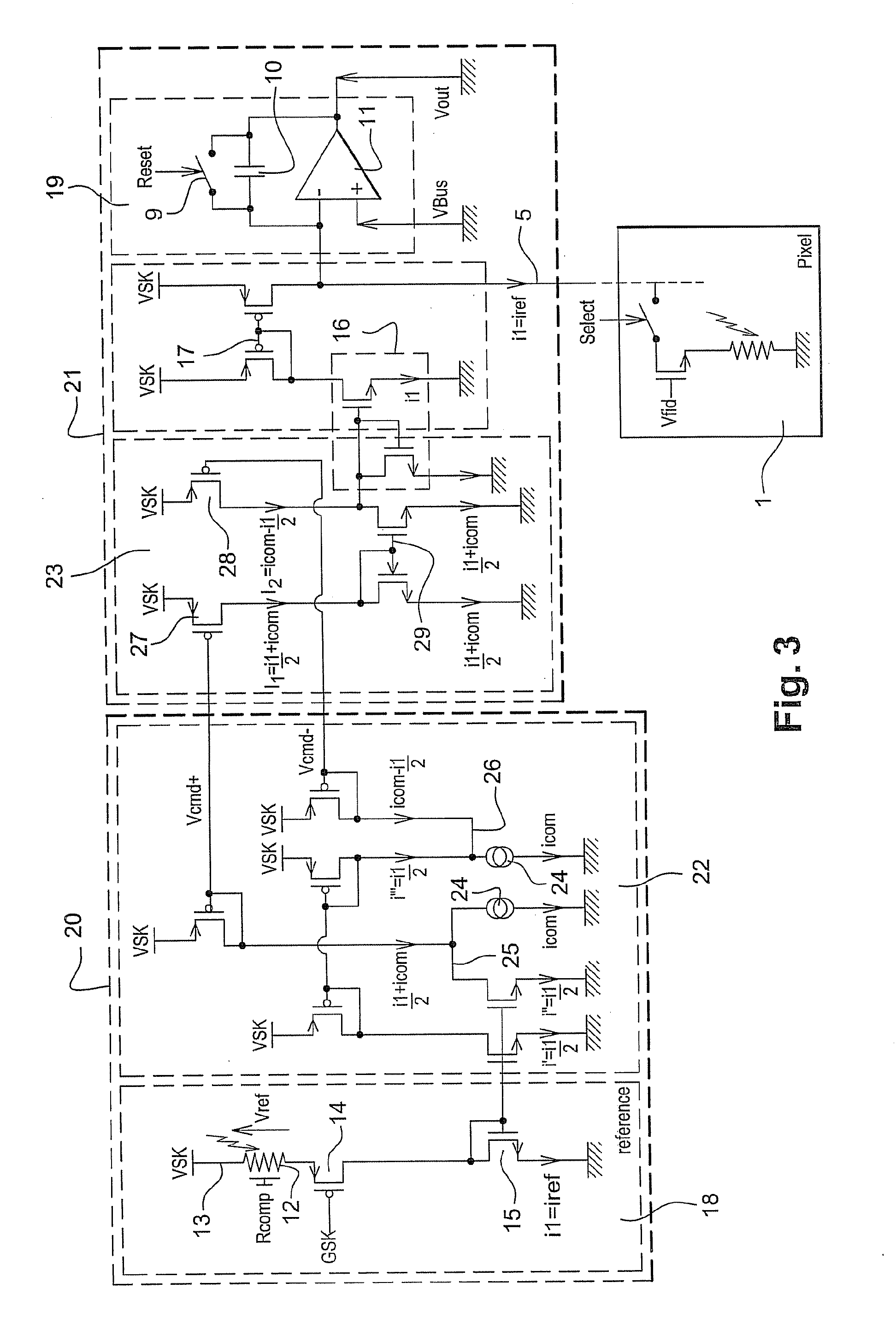
[0058]In other words, the entire array of bolometers is compensated by a single structure which thus makes it possible to prevent the columnar contrast which is observed when using detectors according to the prior art.

Problems solved by technology

The essential difficulty encountered when using bolometric detectors is the extremely small relative variation in their electrical resistance which is representative of the local temperature variations in an observed scene relative to the average value of these resistances.
Residual fluctuations in the temperature of the substrate under normal thermal stabilization conditions, all the more so if the detector does not have such a thermal stabilization system as is increasingly the case with this type of detector in order to reduce its cost, consequently produce an unwanted component in the signal obtained from the bolometer which adversely affects the quality of the signal.
In addition, blind bolometers, like imaging bolometers, as well as certain functions of the read circuit, are affected by noise phenomena in general and so-called “1 / f” noise in particular.
1 / f noise typically produces low-frequency drift, especially very low frequency drift, of the output level of the sensors which adversely affects the quality of the imager.
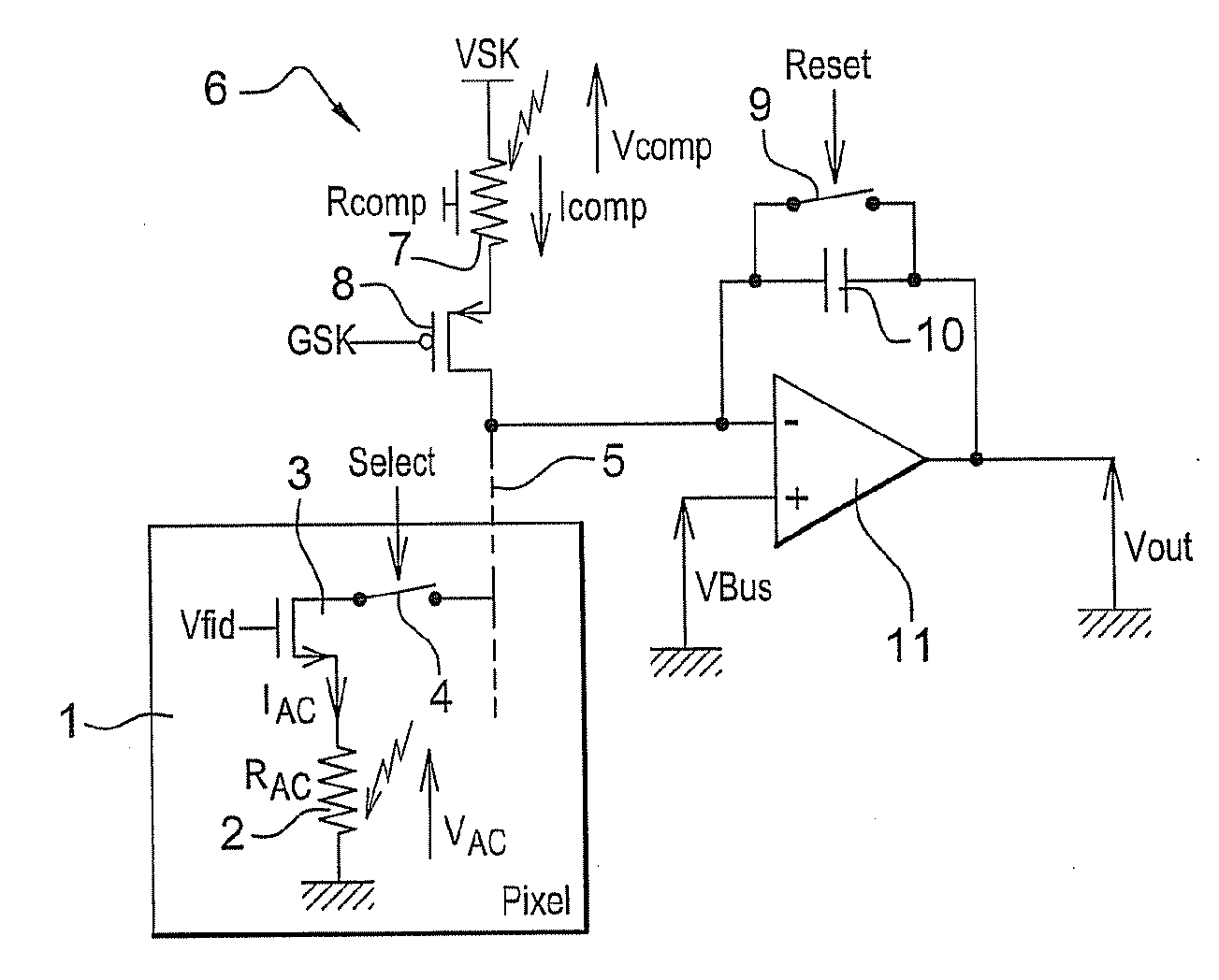
The columnar arrangement of the compensation structures has a negative impact on the quality of the image because of low-frequency variations in the compensated signal which are asynchronous from one column to the next.
This read system has certain limitations associated with the way in which the columnar compensation pattern is reproduced on the read circuit.
Imperfect reproduction of these various elements from one column to the next which is inherent in the intrinsic spatial variability of the fabrication technologies used results in non-uniform compensation efficiency.
This statistical variability results in a compensation current which is not uniform from one column to the next and causes the appearance of visible columnar contrasts which thus affect the available signal.
Many parameters in this equation may vary, thus producing columnar non-uniformity of the compensation current.
Fluctuation in the length of the channel is also one of the possible causes of this non-uniformity.
In contrast, variation in threshold voltage VthP poses a problem.
Beside this limitation, the market trend towards bolometric sensors with an increased number of pixels means that the compensation bolometers of each column, which are effective in small imagers as an absolute temperature reference, act as “local” temperature references from the point of view of the active bolometers which are the furthest away.

Method used


Image

  • Device for detecting infrared radiation with bolometric detectors
  • Device for detecting infrared radiation with bolometric detectors
  • Device for detecting infrared radiation with bolometric detectors

Examples


Embodiment Construction

[0070]In the rest of this description, the same reference number is used to identify elements which are identical or of the same functional type, when applicable.

[0071]Generally speaking and as already stated, the array of bolometric detectors is formed on a silicon substrate in which the read circuit is produced. This substrate is traditionally covered, in the area of its active structures, i.e. vertically below the optically sensitive area, in a reflective metallic layer. This layer is designed, in a known manner, to form a quarter-wave cavity between the substrate and the absorbent parts of the detector.

[0072]The optically active areas are formed by “paved” suspended membranes which comprise, above the read circuit, a bolometric material. These membranes are supported by means of structures which are substantially vertical and electrically conductive. These structures, made of a metallic material, are also designed to route the excitation potentials generated by the read circuit ...


PUM


Abstract

A device for detecting infrared radiation comprising an array of bolometric detectors which are sensitive to incident radiation and are referred to as “active” and a bolometer which is insensitive to said radiation and is referred to as “blind” formed on a substrate in which a read circuit is produced for sequentially addressing each of the rows of detectors of the array, each of the active bolometers in a single row being biased simultaneously. The read circuit also comprises means of producing a reference current (Iref) based on the blind bolometer; means of simultaneously copying the reference current (Iref) for each column of the array; and a plurality of current integrators, each associated with one column of the array and each designed to integrate the difference between the current flowing through the active bolometer of the row which is currently being read and said thus copied reference current.

Description

FIELD OF THE INVENTION[0001]The present invention relates to a device for detecting infrared radiation which uses bolometric detectors. The application area of the invention is infrared imaging in particular.DESCRIPTION OF THE PRIOR ART[0002]In the field of infrared detectors, the use of devices designed in the form of an array which are capable of operating at ambient temperature, i.e. which do not require cooling down to very low temperatures, is known—these are contrasted with detection devices referred to as “quantum infrared detectors” which can only operate at very low temperature, typically at the temperature of liquid nitrogen.[0003]These uncooled detectors traditionally use the variation in a physical unit of an appropriate material as a function of temperature at around 300 K. In the case of bolometric detectors, this physical unit is electrical resistivity.[0004]Such an uncooled detector is generally associated with:[0005]means of absorbing the infrared radiation and conv...

Claims


Application Information

Patent Timeline
Patent Type & Authority Applications(United States)
IPC IPC(8): G01J5/00H04N25/00
CPCG01J5/22H04N5/3653H04N5/361H04N5/33H04N25/672H04N25/63
Inventor DUPONT, BENOITVILAIN, MICHEL
Owner ULIS SAS
Learn More