Bearing apparatus and centrifugal compressor provided with same

a technology of bearing apparatus and centrifugal compressor, which is applied in the direction of magnetic bearings, machines/engines, liquid fuel engines, etc., can solve the problems of complex construction of suppressing wear of foil bearings and worn foil bearings, and achieve the effect of suppressing wear of foil bearings and simple construction

Inactive Publication Date: 2009-01-08
JTEKT CORP
View PDF2 Cites 13 Cited by
  • Summary
  • Abstract
  • Description
  • Claims
  • Application Information

AI Technical Summary

Benefits of technology

[0009]This invention has been made in view of the above circumstances, and an object of the invention is to provide a bearing apparatus in which in a condition in which a sufficient dynamic pressure to cause a rotating member to float off a foil bearing is not obtained, wear of the foil bearing can be suppressed with a simple construction. Another object of the invention is to provide a centrifugal compressor provided with such a bearing apparatus.

Problems solved by technology

Therefore, there has been encountered a problem that the foil bearing is worn.
However, in the above conventional technique, a jet of compressed air is supplied at the time of starting the rotation, and therefore the through hole must be formed in the foil bearing, etc., and in addition to the rotating member and the foil bearing, means for supplying a jet of compressed air must be provided, and therefore there has been encountered a problem that the construction of suppressing wear of the foil bearing becomes complicated.

Method used


Image

  • Bearing apparatus and centrifugal compressor provided with same
  • Bearing apparatus and centrifugal compressor provided with same
  • Bearing apparatus and centrifugal compressor provided with same

Examples


Embodiment Construction

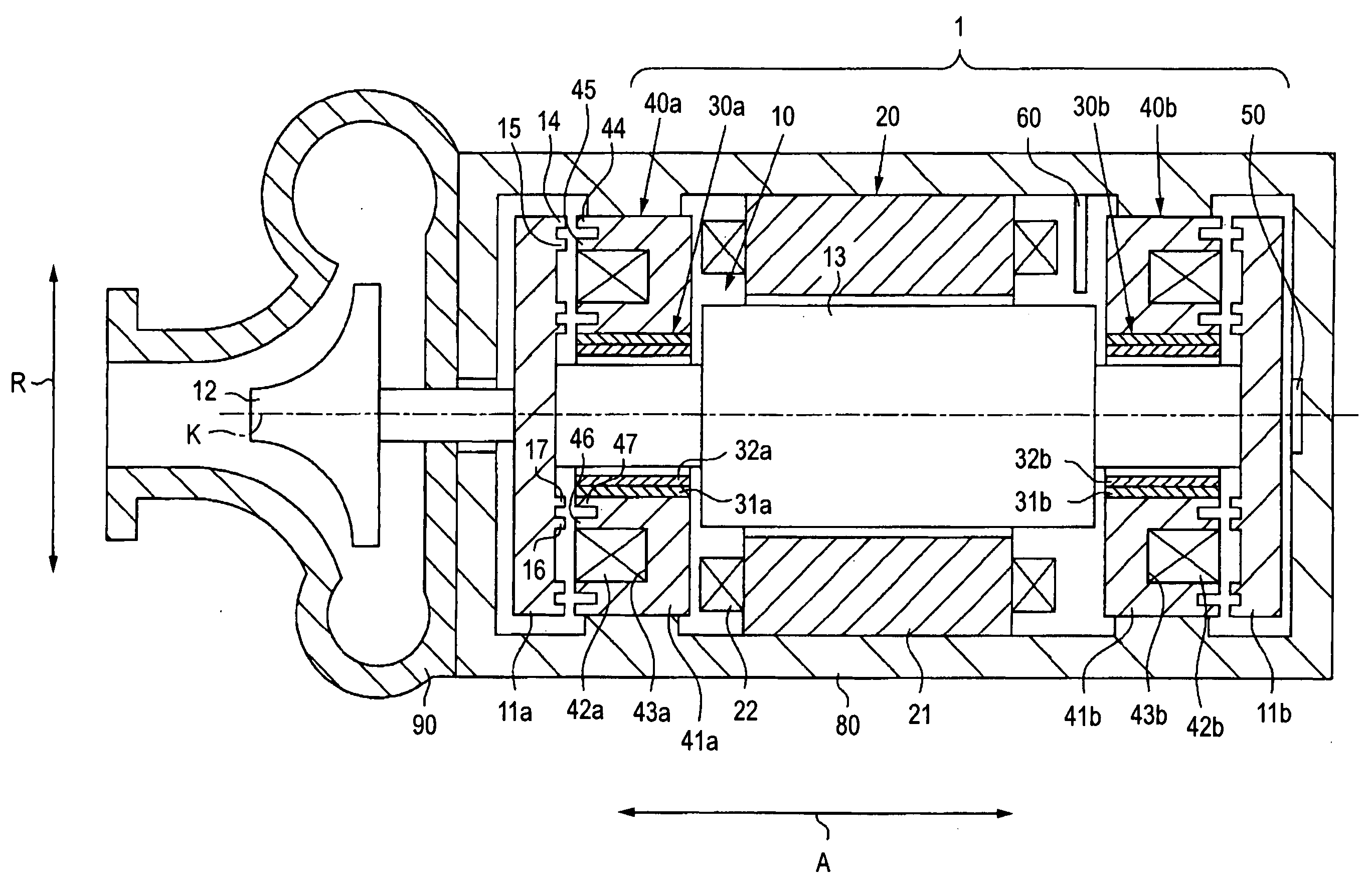
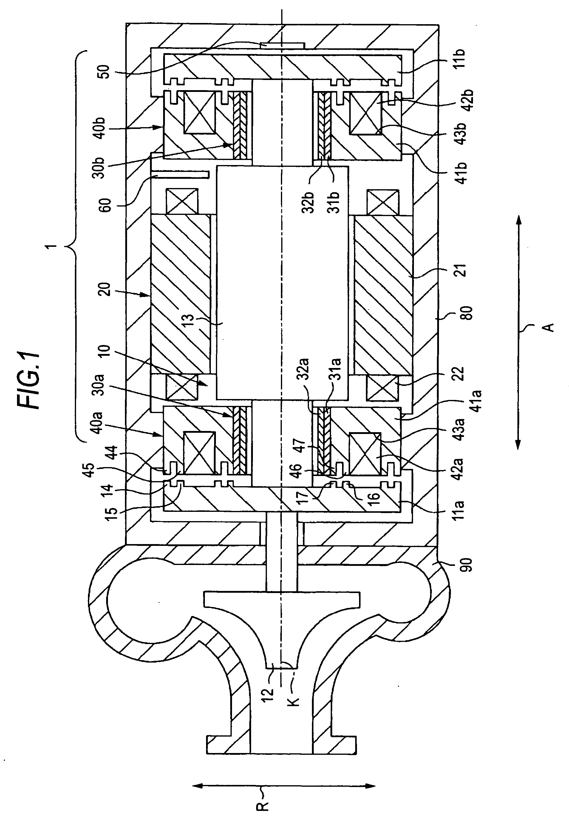
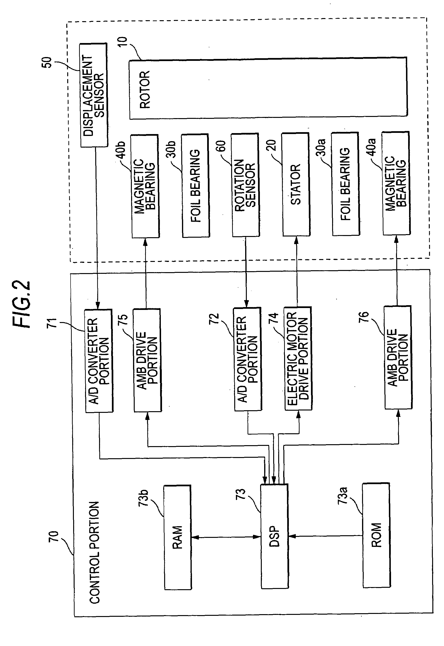
[0035]One preferred embodiment of a bearing apparatus of the present invention will now be described with reference to the drawings. FIG. 1 is a schematic view showing an overall construction of a centrifugal compressor provided with the bearing apparatus of the invention. As shown in FIG. 1, the bearing apparatus 1 comprises a rotor (rotating member) 10, a stator 20 for producing a rotating magnetic field for rotating the rotor 10, and foil bearings 30a and 30b and magnetic bearings 40a and 40b which rotatably support the rotor 10. An electric motor is formed by the rotor 10 and the stator 20. The bearing apparatus 1 further comprises a displacement sensor 50 for detecting the position of the rotor 10 in an axial direction (which is parallel to a rotation axis K of the rotor 10, and is indicated by arrow A in FIG. 1), and a rotation sensor (detector) 60 for detecting the number of revolutions of the rotor 10 per unit time (hereinafter referred to merely as “the number of revolution...


PUM


Abstract

A bearing apparatus include a rotor having a flange portion, a foil bearing for supporting the rotor in a radial direction, and a magnetic bearing for supporting the rotor in an axial direction by an electromagnet, and a control portion for controlling electric current supplied to the electromagnet. The control portion controls such that a first electric current is supplied to the electromagnet so as to cause the electromagnet to attract the flange portion so as to support the rotor in the axial direction. The control portion also controls such that when the number of revolutions of the rotor is smaller than the number (R1) of revolutions at which the rotor floats off the foil bearing when supplying the first electric current to the electromagnet, a second electric current larger than the first electric current is supplied to the electromagnet.

Description

BACKGROUND OF THE INVENTION[0001]1. Field of the Invention[0002]This invention relates to a bearing apparatus designed to suppress wear of a foil bearing, and also relates to a centrifugal compressor provided with this bearing apparatus.[0003]2. Related Art[0004]Generally, it is known to use a bearing apparatus for rotatably supporting a rotating member in a rotating machine such for example as a compressor and a blower. A rolling bearing, a slide bearing or the like can be used as a bearing employed in the bearing apparatus. However, in order to suppress contact of the rotating member with the bearing so as to prolong a life of the bearing apparatus, generally, a magnetic bearing or a foil bearing which is a non-contact bearing (that is, a bearing for supporting the rotating member in a non-contact manner) has been used.[0005]As one example of bearing apparatuses employing a foil bearing (non-contact bearing), there is known one in which the foil bearing is used as a bearing for su...

Claims


Application Information

Patent Timeline
Patent Type & Authority Applications(United States)
IPC IPC(8): F16C32/04
CPCF04D29/051F04D29/057F04D29/058F16C2360/42F16C32/0402F16C32/044F16C17/024F16C32/0476
Inventor MIYAGAWA, YASUKATAUEYAMA, HIROCHIKATANIGUCHI, MANABU
Owner JTEKT CORP
Why Eureka
Try Eureka