Control apparatus

a control apparatus and control technology, applied in the direction of electric programme control, program control, instruments, etc., can solve the problems of falling machining precision of machine tools, natural frequency changes, and prone to arise, so as to reduce the natural vibration of the controlled object and accurately detect the

Active Publication Date: 2009-01-08
FANUC LTD
View PDF5 Cites 33 Cited by
  • Summary
  • Abstract
  • Description
  • Claims
  • Application Information

AI Technical Summary

Benefits of technology

[0020]Therefore, an object of the present invention is to provide a control apparatus accurately detecting a natural frequency of a controlled object driven by an electric motor and reducing natural vibration of the controlled object.
[0031]According to the above explained control apparatus of the present invention, it is possible to accurately detect the natural frequency of the controlled object driven by the electric motor and reduce the natural vibration of the controlled object.

Problems solved by technology

Further, if vibration occurs due to resonance, problems are liable to arise such as the machining precision of the machine tool falling or the held workpiece detaching from the hand.
Further, sometimes individual differences in machines result in changes in the natural frequency.
Further, sometimes the natural frequency changes due to aging of the machine.
However, with just continuously detecting the position of the controlled object etc. and detecting the natural frequency of the controlled object as in the control apparatus described in Japanese Patent Publication (A) No. 7-261853 or Japanese Patent Publication (A) No. 2001-293638, due to the following reasons, sometimes it is not possible to accurately detect the natural frequency affecting the operation of the controlled object.
Further, depending on the state of the controlled object, sometimes no resonance occurs due to the natural frequency, so even if trying to detect it, sometimes it is not possible to detect the natural frequency of the controlled object.
Further, in processing for reducing the natural vibration of a controlled object, sometimes the controlled object is made unstable.
As one example, when not able to detect the accurate natural frequency, but detecting the mistaken natural frequency and changing the settings of the filter accordingly, sometimes the controlled object becomes unstable.
As another example, even if detecting the accurate natural frequency, when the natural frequency is close to the control band, sometimes the filter strips part of the signal of the control band so again the controlled object becomes unstable.
Still further, there is a demand that the control apparatus stably control the control object under conditions of a limited storage capacity of the apparatus and limited time for control processing.
These are issues which should be dealt with after the control apparatus accurately detects the natural frequency of the controlled object.

Method used


Image

  • Control apparatus
  • Control apparatus
  • Control apparatus

Examples


first embodiment

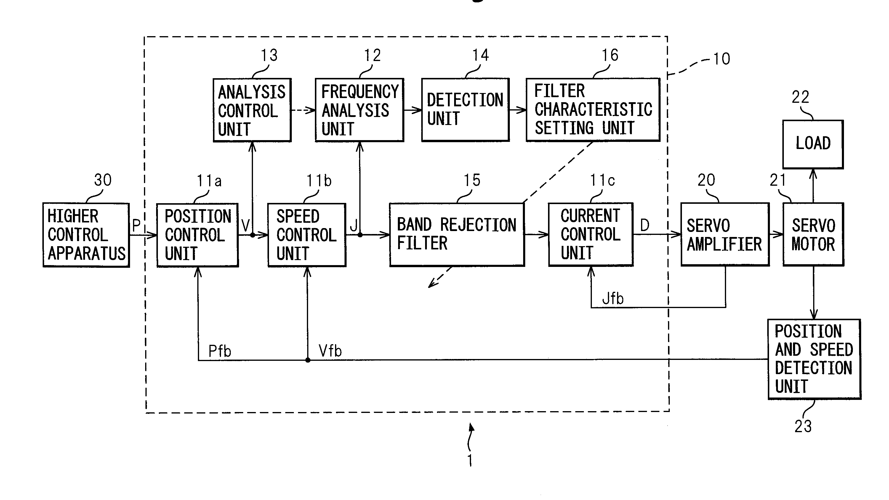
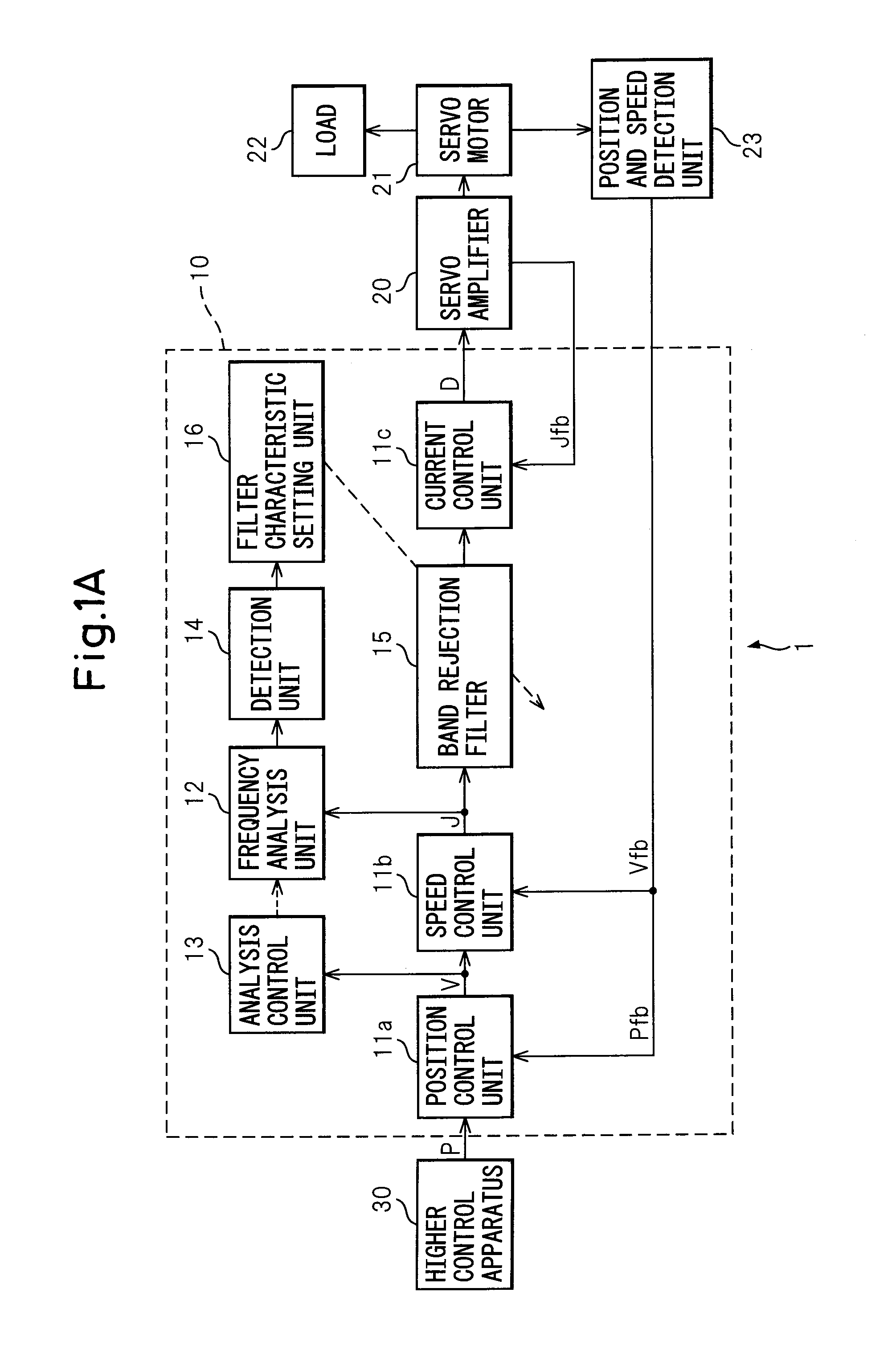
[0044]The control apparatus 10 of the first embodiment of the present invention (below, also referred to as the “present apparatus 10”) is a control apparatus of a machine tool 1. As shown in FIG. 1A, it receives a control signal from a higher control apparatus 30, that is, a position command P, controls the electric motor of the servo motor 21 through a servo amplifier 20, and drives the driven part, that is, the load 22, to control the operation.

[0045]The present apparatus 10, as shown in FIG. 1A, has a control unit outputting a control signal controlling a servo motor 21 and suppresses natural vibration of the controlled object, including the servo motor 21 and machine driven by the servo motor 21, while controlling the controlled object. Further, the present apparatus 10 has a frequency analysis unit 12 analyzing a frequency included in a control signal of a torque command, an analysis control unit 13 controlling the start or stopping of the frequency analysis unit 12, a detecti...

second embodiment

[0081]The control apparatus 10 of the second embodiment of the present invention (below, also referred to as the “the present apparatus 10”), as shown in FIG. 2, has a higher control apparatus 30 controlling the analysis control unit 13. When the higher control apparatus 30 outputs a start command to the analysis control unit 13, the analysis control unit 13 makes the frequency analysis unit 12 analyze the frequency. The higher control apparatus 30 of the present apparatus 10, in the same way as the above first embodiment, outputs the position command P to the position control unit 11a and controls the analysis control unit 13.

[0082]Below, the present apparatus 10 will be explained further. When vibration having a large amplitude other than the natural vibration of the controlled object is known, the analysis control unit 13, in the same way as the first embodiment, controls the frequency analysis unit 12 so as not to detect this vibration as natural vibration. However, when vibrati...

third embodiment

[0092]In the control apparatus 10 of the third embodiment of the present invention (below, also referred to as the “present apparatus 10”), the detection unit 14 detects the natural frequency of the controlled object from the predetermined frequency range in the analysis result of the frequency analysis unit 12.

[0093]The present apparatus 10 will be explained below referring to FIG. 3. FIG. 3 shows an example of the analysis result of the frequency analysis unit 12. In FIG. 3, there are the peak PF1, peak PF2, and peak PF3. The magnitudes of the frequency components are at least the threshold value Th by which the detection unit 14 judges the frequency is a natural frequency. The threshold value Th, in the example shown in FIG. 3, has a certain value with respect to the frequency. Here, the peak PF1 and peak PF3 are the natural frequencies of the controlled object, while the peak PF2 is deemed known to be due to the motor cogging of the servo motor 21.

[0094]The fact that the peak PF...


PUM


Abstract

A control apparatus of the present invention comprising a control unit outputting a control signal controlling a servo motor and suppressing natural vibration of a controlled object including a motor and a machine driven by the motor while controlling the controlled object, comprising a frequency analysis unit analyzing a frequency component included in a torque command, an analysis control unit controlling the start or stopping of the frequency analysis unit, a detection unit detecting a natural frequency of the controlled object from an analysis result of the frequency analysis unit, a-band rejection filter receiving as input the torque command, stripping the command of the natural frequency component, and outputting the resultant command to the motor through a current control unit and servo amplifier, and a filter characteristic setting unit setting the frequency to be stripped at the filter based on the natural frequency detected by the detection unit.

Description

[0001]The applicant claims the right to priority based on Japanese Patent Application No. 2007-174296 filed on Jul. 2, 2007, the entire content of which is hereby incorporated by reference.BACKGROUND OF THE INVENTION[0002]1. Field of the Invention[0003]The present invention relates to a control apparatus, more particularly relates to a control apparatus suppressing natural vibration of a controlled object including an electric motor and a machine driven by this electric motor while controlling the controlled object.[0004]2. Description of the Related Art[0005]In the past, machine tools equipped with electric motors have used control apparatuses for controlling the electric motors. In particular, a control apparatus using an electric motor, that is, a servo motor, for feedback control controls the difference between position, speed, current, and other command values and the actual values to become zero at all times. The machine position, motor speed, etc. are accurately controlled, s...

Claims


Application Information

Patent Timeline
Patent Type & Authority Applications(United States)
IPC IPC(8): G05B13/02G05D19/02H02P29/00
CPCG05B13/024G05B19/19G05B2219/41232G05B2219/37534G05B2219/41166G05B2219/34048
Inventor OKITA, TADASHITOYOZAWA, YUKIOSONODA, NAOTO
Owner FANUC LTD
Why Eureka
Try Eureka