

Display control device and method of controlling same
Patent Information
- Authority / Receiving Office
- US · United States
- Patent Type
- Applications(United States)
- Current Assignee / Owner
- RENESAS ELECTRONICS CORP
- Publication Date
- 2009-01-08
- Estimated Expiration
- Not applicable · inactive patent
Smart Images
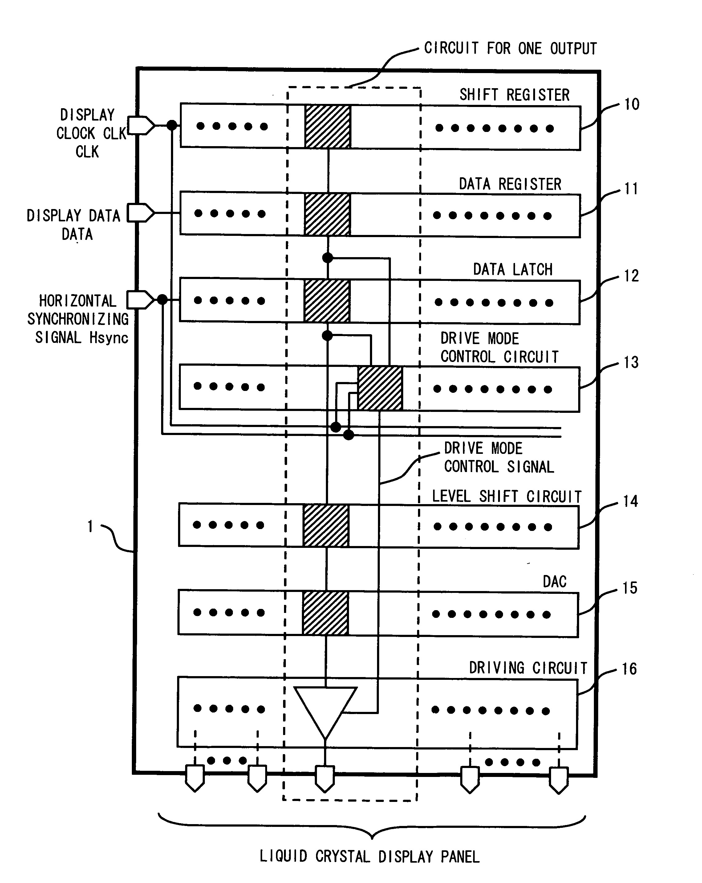
Figure 1 
Figure 2 
Figure 3
Abstract
Description
BACKGROUND OF THE INVENTION
[0001] 1. Field of the Invention
[0002] The present invention relates to a display control device and a method of controlling the same. In particular, the present invention relates to a display control device having periods during which a display device is driven by different current driving capabilities, and a method of controlling the same.
[0003] 2. Description of Related Art
[0004] In recent years, a liquid crystal display panel such as a TFT (Thin Film Transistor) display panel has been often used as a display device. In the liquid crystal display panel, data is displayed, in general, by driving pixels arranged in a lattice pattern by a gate driver and a source driver. The gate driver has the same number of outputs as the number of rows of the pixels of the liquid crystal display panel, and selects a row of the pixels where data is displayed. The source driver has the same number of outputs as the number of columns of the pixels of the liquid crystal display...