Optical Information Recording Medium, and Recording Method and Manufacturing Method Thereof

Inactive Publication Date: 2009-01-08
SUMITOMO ELECTRIC IND LTD
View PDF2 Cites 29 Cited by
  • Summary
  • Abstract
  • Description
  • Claims
  • Application Information

AI Technical Summary

Benefits of technology

[0033]According to the present invention, since a large change in refractive index can be attained by irradiation of a highly durable DLC layer with an energy beam, it is possibl

Problems solved by technology

However, there is a limit to reduction of wavelength of a laser beam for recording, and various other recording methods are attempted

Method used


Image

  • Optical Information Recording Medium, and Recording Method and Manufacturing Method Thereof
  • Optical Information Recording Medium, and Recording Method and Manufacturing Method Thereof
  • Optical Information Recording Medium, and Recording Method and Manufacturing Method Thereof

Examples


Example

FIRST EMBODIMENT

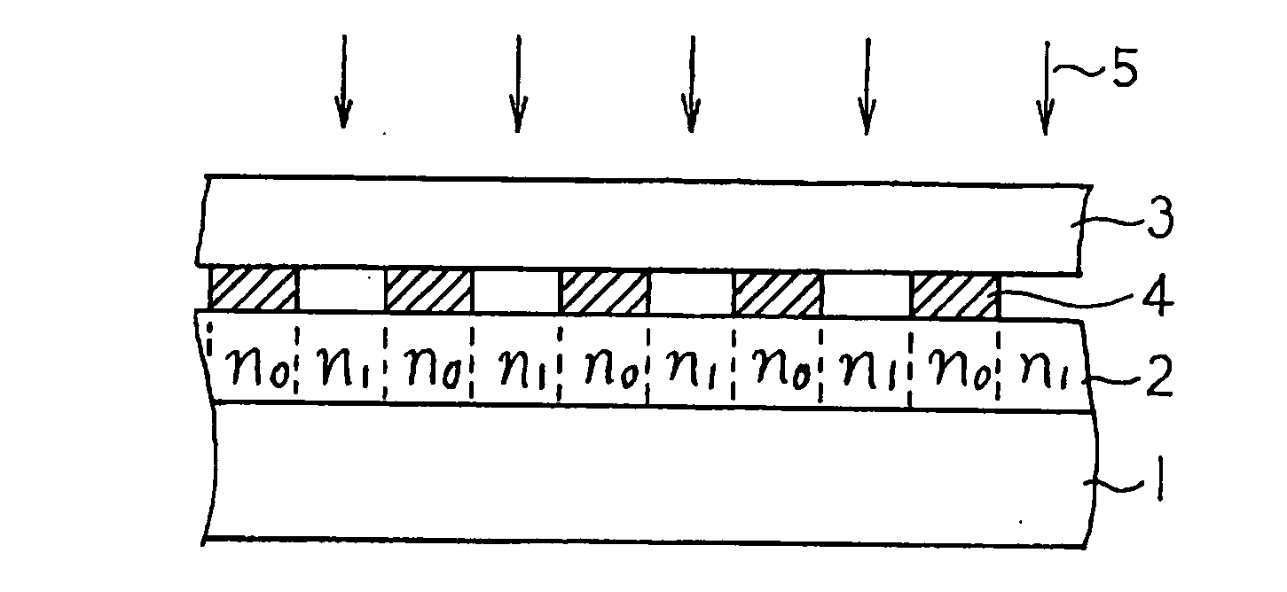
[0046]FIG. 1 is a schematic cross-sectional view illustrating a method of making an optical information-recording medium according to a first embodiment of the present invention and a method of recording information. In the first embodiment, a DLC layer 2 is deposited on a glass substrate 1 by a known plasma CVD process to a thickness of, for example, 1 μm. A chromium film is deposited on another glass substrate 3 by, for example, vapor deposition and subjected to stepper exposure and etching to form a patterned chromium film which serves as a metal film mask pattern 4. The metal film mask pattern 4 includes a plurality of micro apertures corresponding to a plurality of recording spot regions.

[0047]The metal film mask pattern 4 thus prepared is placed on the DLC layer 2. Then, for example, a UV ray 5 having a wavelength of 250 nm and an energy density of 20 mW / mm2 is applied to the DLC layer 2 through the metal film mask pattern 4 for about one hour. As a result, the...

Example

SECOND EMBODIMENT

[0049]In a second embodiment of the present invention, multilevel recording is conducted in an optical information-recording medium including a DLC layer. In the second embodiment, binary recording is first conducted as in the first embodiment illustrated in FIG. 1.

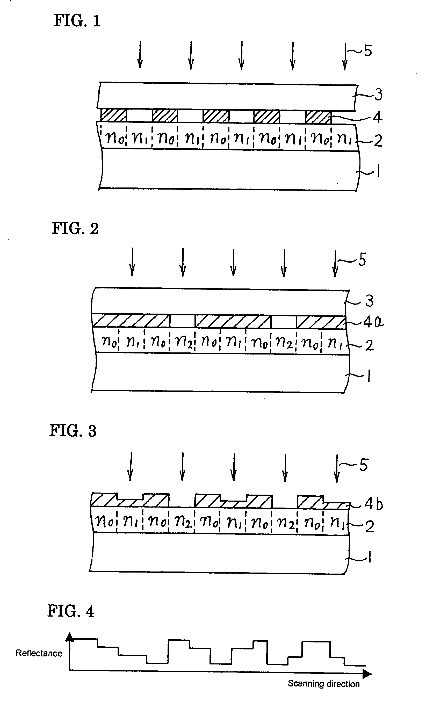
[0050]Subsequently, as shown in the schematic cross-sectional view in FIG. 2, a second metal film mask pattern 4a is placed on the DLC layer 2. The second metal film mask pattern 4a includes micro apertures that correspond to recording spot regions selected from the recording spot regions having a refractive index increased to n1. The DLC layer 4 is again irradiated with the UV ray 5 through the second metal film mask pattern 4a.

[0051]As a result, the refractive index of the recording spot regions irradiated with the UV ray 5 through the apertures in the second metal film mask pattern 4a further increases from n1 to n2. In this manner, ternary signals can be recorded. As is evident from the above, furthe...

Example

THIRD EMBODIMENT

[0052]FIG. 3 is a schematic cross-sectional view illustrating a method of making an optical information-recording medium according to a third embodiment of the present invention and a method of recording information. In the third embodiment also, the DLC layer 2 is deposited on the glass substrate 1 by plasma-enhanced CVD.

[0053]However, a chromium film is deposited on the DLC layer 2 and subjected to stepper exposure and etching to form a patterned chromium film, which serves as a metal film mask pattern 4b. In this case, the stepper exposure and etching are conducted in two or more stages so that, in the example shown in FIG. 3, the thickness of the metal film mask pattern 4b is varied in three levels including zero in a plurality of micro regions corresponding to a plurality of recording spot regions. The DLC layer 4 is irradiated with the UV ray 5 through this metal film mask pattern 4b.

[0054]Although the UV ray 5 cannot pass through the thickest regions in the m...


PUM


Abstract

To provide an optical information-recording medium that can easily record information at high density and has excellent durability at low cost.
The optical information-recording medium includes a diamond-like carbon (DLC) layer (2) deposited on a substrate (1), in which information is recorded on the optical information-recording medium by irradiating recording spot regions selected from a plurality of recording spot regions with an energy beam (5) to increase the refractive index of the DLC layer (2) in the irradiated recording spot regions.

Description

TECHNICAL FIELD[0001]The present invention relates to optical information-recording media, in particular, an optical information-recording medium which facilitates high density recording and has high durability.BACKGROUND ART[0002]Compact disks (CDs) and digital versatile discs (DVD) are typical examples of optical information-recording media put to practical application known today. However, today's highly information-oriented society demands optical information-recording media to achieve higher recording density. The recording density of optical information media can be increased by decreasing the wavelength of a light beam used for reading and writing. From this standpoint, blue ray discs in which data is written using a blue laser is under development. However, there is a limit to reduction of wavelength of a laser beam for recording, and various other recording methods are attempted to increase the recording density of optical information-recording media (refer to Nonpatent Doc...

Claims


Application Information

Patent Timeline
IPC IPC(8): G11B7/00G11B7/24044
CPCG03H1/02G03H1/0408G03H1/182G11B7/26G03H2001/2615G03H2240/54G11B7/24044G03H2001/0268G11B7/0065
Inventor USHIRO, TOSHIHIKOODA, KAZUHIKOMATSUURA, TAKASHI
Owner SUMITOMO ELECTRIC IND LTD
Why Eureka
Try Eureka