Multilayer ceramic substrate, method for producing same, and electronic component

a multi-layer ceramic and substrate technology, applied in the direction of natural mineral layered products, solid-state devices, electrical devices, etc., can solve the problems of failure to disclose any limitations on the difference in thermal expansion coefficient, increase in the stress at the interface between the outermost layer and the inner layer, and delamination and voids. , to achieve the effect of reducing warpage and increasing strength

Active Publication Date: 2009-01-08
MURATA MFG CO LTD
View PDF7 Cites 20 Cited by
  • Summary
  • Abstract
  • Description
  • Claims
  • Application Information

AI Technical Summary

Benefits of technology

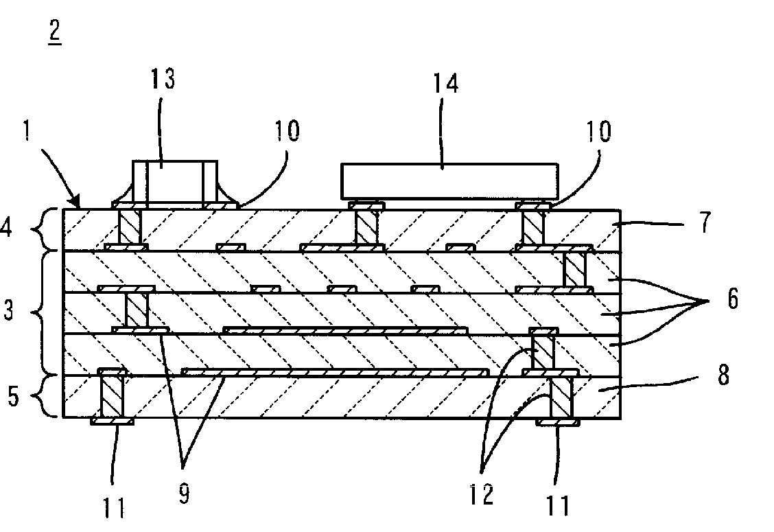
[0009]To overcome the problems described above, preferred embodiments of the present invention provide a multilayer ceramic substrate having increased strength and reduced warpage, a method for producing the multilayer ceramic substrate, and an electronic component including the multilayer ceramic substrate.
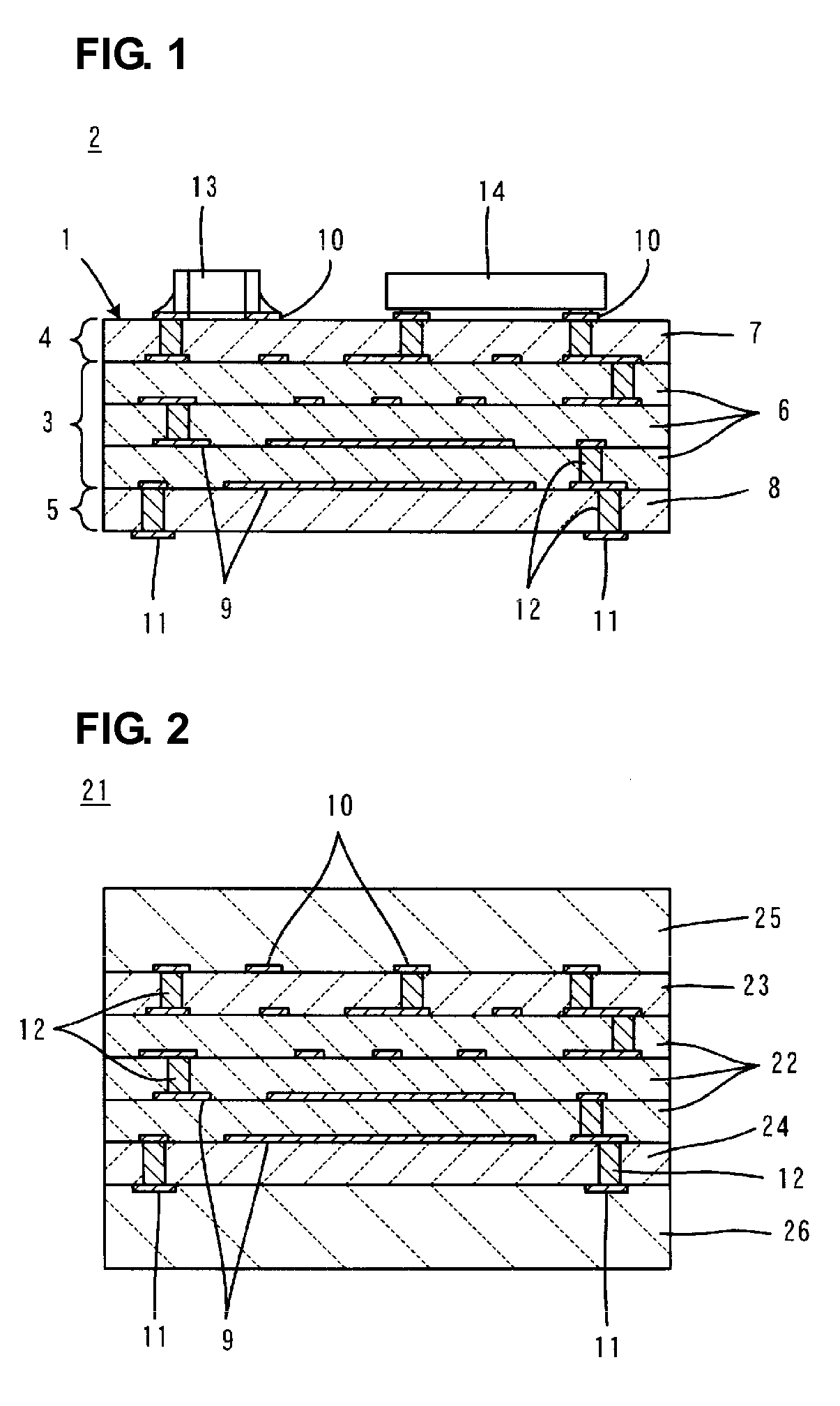
[0016]In the method for producing the multilayer ceramic substrate according to a preferred embodiment of the present invention, surface ceramic green sheets to form surface layers, an inner ceramic green sheet to form an inner layer, and a restraint ceramic green sheet to restrain shrinkage, the restraint ceramic green sheet including an inorganic material that is not sintered at a temperature at which the surface ceramic green sheets and the inner ceramic green sheet are sintered are prepared.
[0021]In the multilayer ceramic substrate according to preferred embodiments of the present invention, the thermal expansion coefficient of the surface layer portions is less than the thermal expansion coefficient of the inner layer portion, to generate compressive stresses in the surface layer portions during a cooling step after the firing and to improve the transverse strength of the multilayer ceramic substrate in a similar manner as in Japanese Unexamined Patent Application Publication No. 6-29664.
[0023]Furthermore, in the multilayer ceramic substrate according to preferred embodiments of the present invention, the weight content of a component common to both a material from which the surface layer portions is made and a material from which the inner layer potion is provided is at least about 75% by weight, thus providing sufficient bonding strength between the surface layer portions and the inner layer portion. As described above, therefore, even with a large difference in thermal expansion coefficient between the surface layer portions and the inner layer portion of at least about 1.0 ppmK−1, for example, defects, such as delamination and voids, are prevented from occurring.
[0024]In the multilayer ceramic substrate according to preferred embodiments of the present invention, a difference in thermal expansion coefficient between the surface layer portions and the inner layer portion of about 4.3 ppmK−1 or less, for example, prevents defects, such as delamination and voids, caused by the difference in thermal expansion coefficient.
[0025]In the method for producing a multilayer ceramic substrate according to preferred embodiments of the present invention, a composite laminate provided with the restraint ceramic green sheet on each of the main surface of the composite laminate is fired. This suppresses or prevents the shrinkage of the surface ceramic green sheets and the inner ceramic green sheet in the direction of the main surface during the firing. As a result, undesired deformations of the multilayer ceramic substrate are prevented so as to improve the dimensional accuracy of the multilayer ceramic substrate. Furthermore, the delamination between the inner layer portion and the surface layer portions is much less likely to occur during the firing.

Problems solved by technology

However, the multilayer ceramic substrate described in Japanese Unexamined Patent Application Publication No. 6-29664 has the problems described below.
Simply increasing the thermal expansion coefficient between the outermost layers and the inner layers may increase the stress at the interfaces between the outermost layers and the inner layers, which can cause defects, such as delamination and voids, for example, at the interfaces.
However, Japanese Unexamined Patent Application Publication No. 6-29664 fails to disclose any limitations on the difference in thermal expansion coefficient.
When using the structure described in Japanese Unexamined Patent Application Publication No. 6-29664, an increase in the difference in thermal expansion coefficient results in an increase in the stress at the interfaces between the outermost layers and the inner layers.
If the bonding strength is insufficient at the interfaces, defects such as delamination and voids, for example, due to the stress may occur at the interfaces.
Where a component is mounted on or a resin coating is performed on a surface of the multilayer ceramic substrate, the shrinkage of solder, an adhesive, or the coating resin disadvantageously may cause warpage of the multilayer ceramic substrate.

Method used


Image

  • Multilayer ceramic substrate, method for producing same, and electronic component
  • Multilayer ceramic substrate, method for producing same, and electronic component

Examples


experimental example 1

[0067]Surface ceramic green sheets and inner ceramic green sheets were prepared.

[0068]Table 1 shows the contents of a ceramic powder (in this experimental example, an Al2O3 powder was used) that functions as a filler and the compositions and the contents of glass powders in the surface ceramic green sheets. Table 2 shows the contents of a ceramic powder (an Al2O3 powder) that functions as a filler and the compositions and the contents of glass powders in the inner ceramic green sheets.

TABLE 1Ceramic green sheet for forming surface layerCeramicGlass powderSamplepowderSiO2B2O3CaOMgOZnOAl2O3TiO2SiO2:MO150455040100015.9:14.123030100203001018.0:12.03603820220105519.0:11.0440605152000018.9:11.1520605152000018.9:11.1640463014005523.0:7.0 750455040100015.9:14.18603820220105519.0:11.0940463014005523.0:7.0 105030100203001018.0:12.0114073423000022.8:7.2 1250605152000018.9:11.113603451610530017.0:13.01450545301100017.1:12.91540463014005523.0:7.0 165073423000022.8:7.2 1740601025005021.2:8.8 1850...

experimental example 2

[0083]Surface ceramic green sheets defining surface layers and inner ceramic green sheets defining inner layers were prepared.

[0084]Table 4 shows the compositions and the contents of ceramic raw material powders included in the surface ceramic green sheets. Table 5 shows the compositions and the contents of ceramic raw material powders included in the inner ceramic green sheets.

TABLE 4Ceramic green sheet forforming surface layerSampleBi2O3MgOCaONb2O5SiO221502003002250155300235010103002450812300254003525026401025250274010252502845525250294003525030350353003135035300

TABLE 5Ceramic green sheet forforming inner layerSampleBi2O3MgOCaONb2O5SiO2215030020022503002002350300200245030020025503501502655255150276020101502840525201029451515205304552025531450202015

[0085]To prepare the surface ceramic green sheets and the inner ceramic green sheets for samples 21 to 31, the ceramic raw material powders and water were sufficiently mixed. The mixture was dried and subjected to a heat treatment at abo...


PUM

PropertyMeasurementUnit
thicknessaaaaaaaaaa
thicknessaaaaaaaaaa
thicknessaaaaaaaaaa

Abstract

A multilayer ceramic substrate having high transverse strength, minimized warpage, and no delamination, has a laminated structure including an inner layer portion and surface layer portions, in which the thermal expansion coefficient of the surface layer portions is lower than the thermal expansion coefficient of the inner layer portion, the difference in thermal expansion coefficient between the surface layer portions and the inner layer portion is about 1.0 ppmK−1 or more, and the weight content of a component common to both a material constituting the surface layer portions and a material constituting the inner layer portion is about 75% by weight or more.

Description

BACKGROUND OF THE INVENTION[0001]1. Field of the Invention[0002]The present invention relates to a multilayer ceramic substrate, a method for producing a multilayer ceramic substrate, and an electronic component including a multilayer ceramic substrate. In particular, the present invention relates to an improvement in the strength of a multilayer ceramic substrate.[0003]2. Description of the Related Art[0004]A multilayer ceramic substrate in the related art is described in, for example, Japanese Unexamined Patent Application Publication No. 6-29664. Japanese Unexamined Patent Application Publication No. 6-29664 discloses a low-temperature co-fired multilayer ceramic substrate including glass and a crystalline material, in which the outermost layers have a thermal expansion coefficient less than the inner layers, and in which the total thickness of the outermost layers arranged on both sides of the substrate is less than the thicknesses of the inner layers. Japanese Unexamined Patent...

Claims


Application Information

Patent Timeline
Patent Type & Authority Applications(United States)
IPC IPC(8): B32B18/00H01L21/473
CPCH05K1/0306Y10T428/24926H05K3/4688H05K2201/068B32B18/00C04B2235/96C04B2237/343C04B2237/58C04B2237/582C04B2237/66C04B2237/704C04B35/63C04B35/6342C04B2235/656C04B2235/6567C04B2237/32C03C3/064C03C3/066C03C3/089C03C3/091C03C8/02C03C8/14H05K3/4629H01L2224/16225H01L2924/19105H05K1/05H05K3/46
Inventor SAKAMOTO, SADAAKI
Owner MURATA MFG CO LTD
Why Eureka
Try Eureka