Minimally invasive lung volume reduction devices, methods, and systems

a technology of lung volume reduction and minimal invasiveness, applied in the field of treating lungs, can solve the problems of affecting the treatment effect of patients with emphysema, damage to air sacs in your lungs, and difficulty in breathing, so as to reduce the radius of curvature

Active Publication Date: 2009-01-08
EKOS CORP
View PDF101 Cites 96 Cited by
  • Summary
  • Abstract
  • Description
  • Claims
  • Application Information

AI Technical Summary

Benefits of technology

[0014]The design of the device facilitates strain relief on both ends of the device. Further the ends of the device in either the delivery or deployed state are more resilient.
[0029]Pursuant to another method of the invention, a method of bending a lung airway of a patient is provided comprising inserting a device into the airway in a delivery configuration and bending the device into a deployed configuration to reduce the radius of curvature of at least a portion the airway.
[0030]Still another method of the invention provides a method of bending a lung airway of a patient comprising inserting an implantable device into the airway in a delivery configuration and bending the device into a deployed configuration to reduce the radius of curvature of at least a portion the airway. In an embodiment, the step of bending can further comprise operating an actuator outside the patient, the actuator being operatively connected to the device. In yet another embodiment, the step of bending further comprising locking the device into the deployed configuration. In still another embodiment, the step of bending further comprises unlocking the device to permit it to return to the delivery configuration. Additionally, in some embodiments, the step of bending can further comprise disconnecting the actuator from the device. Suitable devices for the methods of the invention include devices that comprise a plurality of asymmetric segments, inserting comprises delivering the plurality of asymmetric segments to the airway as well as devices comprising shape memory material. Additionally, the step of bending can further comprise rotating at least one asymmetric segment with respect to at least another asymmetric segment. An additional step of some embodiments of the method can further comprise delivering a catheter and delivering a shape memory element through the catheter. After delivery of the device, according to the methods provided, the device can then bend into a substantially C shape, S shape, spiral shape, coil shape of one or more radiuses, as well as any shape that is within one or more planes. In an additional embodiment of the method, the step of inserting further comprises delivering the device through a working channel of a bronchoscope. In yet another step of the method, the method further comprises retrieving the device from the airway. Embodiments of the method can further provide the step of providing strain relief to an end of the device during deployment. The delivery configuration of the device can be achieved by transforming metal to a martensite phase or by cooling the implant, such as by delivering liquids or gas. Cooled liquids or gases can be at delivered at temperatures that are at or below body temperature, are 37 degrees Celsius or lower in temperature, or at or below zero degrees Celsius. In some methods of the invention, the implant and surrounding tissues are cooled below zero degrees Celsius, or at or below minus fifteen degrees Celsius.

Problems solved by technology

Having emphysema means some of the air sacs in your lungs are damaged, making it hard to breathe.
Smoking has been identified as a major cause, but with ever increasing air pollution and other environmental factors that negatively affect pulmonary patients; the number of people affected by emphysema is on the rise.
High mortality and morbidity may be associated with this invasive procedure.
The lack of atelectasis or lung volume reduction drastically reduces the effectiveness of such devices.
Unfortunately, it can be difficult to control the scarring and to prevent uncontrolled proliferation of scarring.

Method used


Image

  • Minimally invasive lung volume reduction devices, methods, and systems
  • Minimally invasive lung volume reduction devices, methods, and systems
  • Minimally invasive lung volume reduction devices, methods, and systems

Examples


Embodiment Construction

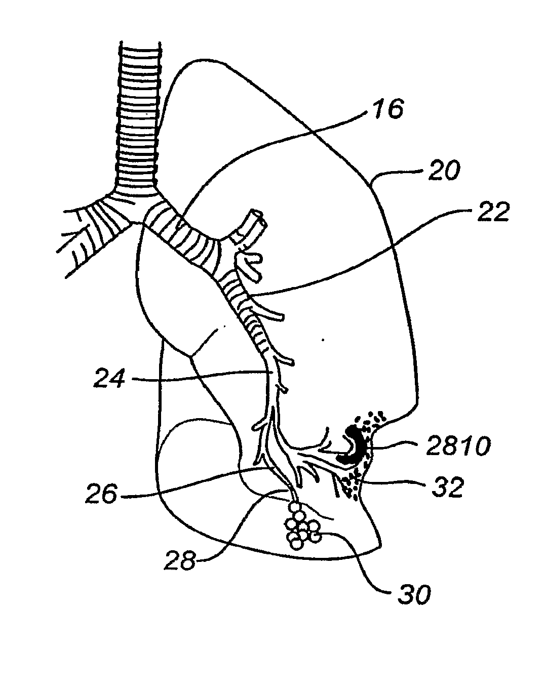
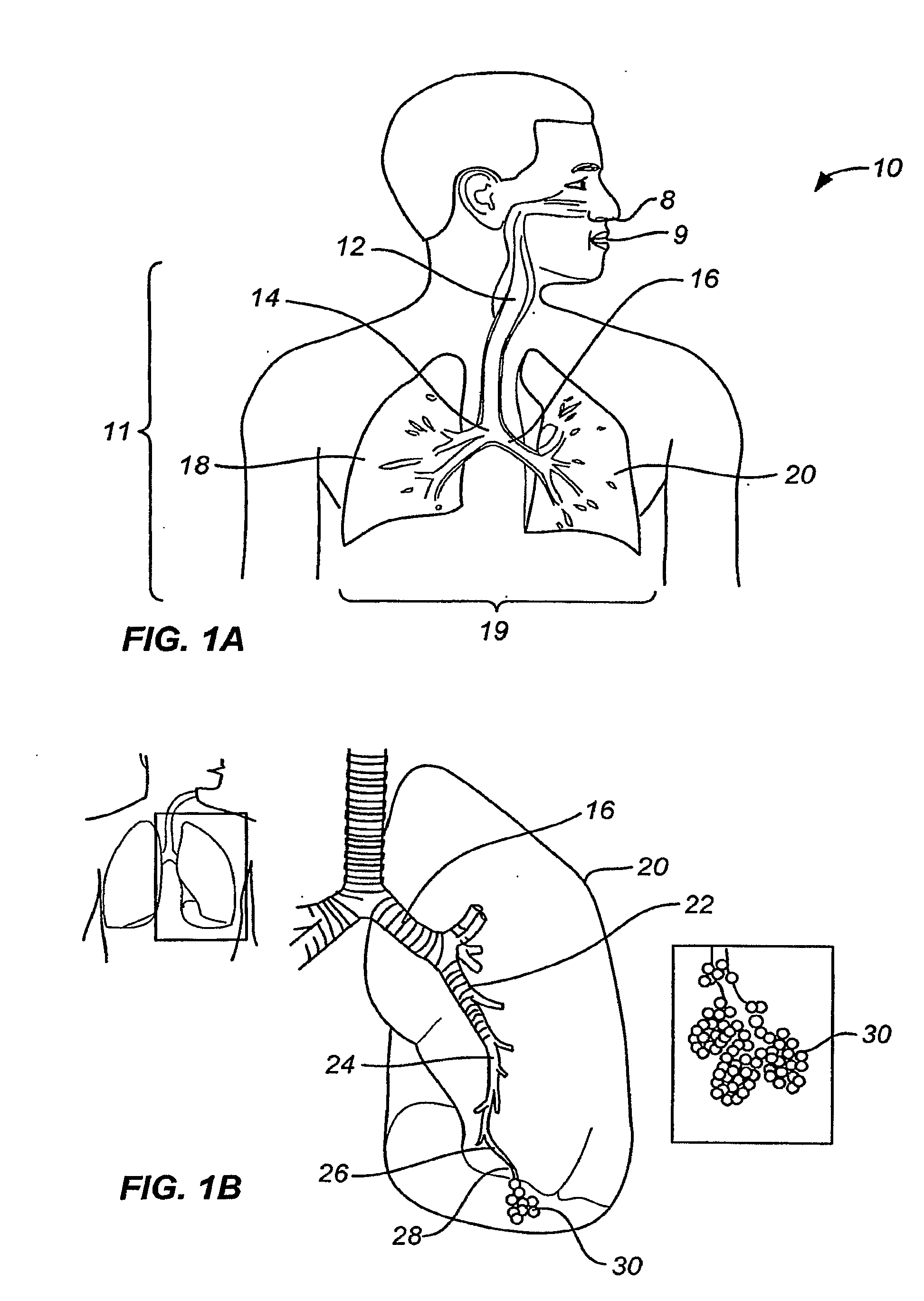
[0087]By way of background and to provide context for the invention, FIG. 1A illustrates the respiratory system 10 located primarily within a thoracic cavity 11. This description of anatomy and physiology is provided in order to facilitate an understanding of the invention. Persons of skill in the art, will appreciate that the scope and nature of the invention is not limited by the anatomy discussion provided. Further, it will be appreciated there can be variations in anatomical characteristics of an individual, as a result of a variety of factors, which are not described herein. The respiratory system 10 includes the trachea 12, which brings air from the nose 8 or mouth 9 into the right primary bronchus 14 and the left primary bronchus 16. From the right primary bronchus 14 the air enters the right lung J 8; from the left primary bronchus 16 the air enters the left lung 20. The right lung 18 and the left lung 20, together comprise the lungs 19. The left lung 20 is comprised of only...


PUM


Abstract

A lung volume reduction system is disclosed comprising an implantable device adapted to be delivered to a lung airway of a patient in a delivery configuration and to change to a deployed configuration to bend the lung airway. The invention also discloses a method of bending a lung airway of a patient comprising inserting a device into the airway in a delivery configuration and bending the device into a deployed configuration, thereby bending the airway.

Description

CROSS-REFERENCES TO RELATED APPLICATIONS[0001]This application is a continuation application of PCT Patent Application No. PCT / US2007 / 006339, filed internationally on Mar. 13, 2007, which is a continuation-in-part of U.S. patent application Ser. No. 11 / 422,047, entitled Minimally Invasive Lung Volume Reduction Device and Method, filed Jun. 2, 2006, which is incorporated herein by reference in its entirety and to which application we claim priority under 35 U.S.C. § 120.[0002]This application claims the benefit of U.S. Provisional Patent Applications 60 / 743,471, entitled Minimally Invasive Lung Volume Reduction Device and Method, filed on Mar. 13, 2006; 60 / 884,804, entitled Minimally Invasive Lung Volume Reduction Devices, Methods and Systems, filed Jan. 12, 2007; and 60 / 885,305, entitled Minimally Invasive Lung Volume Reduction Devices, Methods and Systems, filed Jan. 17, 2007, under 35 U.S.C. § 365, each of which are incorporated herein in their entirety.BACKGROUND OF THE INVENTION...

Claims


Application Information

Patent Timeline
Patent Type & Authority Applications(United States)
IPC IPC(8): A61F2/02A62B7/00A61F2/04
CPCA61B17/12022A61F2002/043A61B17/12131A61B17/12145A61B17/12172A61B2017/00477A61B2017/00809A61M16/04A61M2205/0266A61B1/018A61B1/04A61B1/2676A61B5/06A61B6/032A61B6/12A61B6/485A61B19/00A61M2205/32A61B2017/12054A61M16/0406A61B17/12031A61B2017/00867A61B17/1215A61F2002/046A61B17/1214A61B17/00234A61F2/04A61B19/24A61M37/0069A61B17/12104A61B90/02A61B90/00A61M16/0833A61B1/044A61M16/208
Inventor THOMPSON, DAVIDARONSON, NATHANWU, PATRICKLEHRBERG, DAVIDMATHIS, MARK L.BOUTILLETTE, MICHAELVASQUEZ, JAIME
Owner EKOS CORP
Why Eureka
Try Eureka