Process and apparatus for the separation of a gaseous mixture

a technology of gaseous mixture and process, which is applied in the direction of lighting and heating apparatus, separation processes, liquid degasification, etc., can solve the problems of consuming an excessive amount of energy, consuming and requiring a large amount of energy to capture co2 directly from small and mobile sources

Inactive Publication Date: 2009-01-15
AIR LIQUIDE PROCESS & CONSTRUCTION INC
View PDF8 Cites 74 Cited by
  • Summary
  • Abstract
  • Description
  • Claims
  • Application Information

AI Technical Summary

Problems solved by technology

Capturing CO2 directly from small and mobile sources in the transportation and domestic and commercial buildings sectors is expected to be significantly more difficult and expensive.
In principle, flue gas could be stored, to avoid emissions of CO2 to the atmosphere it would have to be compressed to a pressure of typically more than 100 bar abs and this would consume an excessive amount of energy.

Method used


Image

  • Process and apparatus for the separation of a gaseous mixture
  • Process and apparatus for the separation of a gaseous mixture
  • Process and apparatus for the separation of a gaseous mixture

Examples


Embodiment Construction

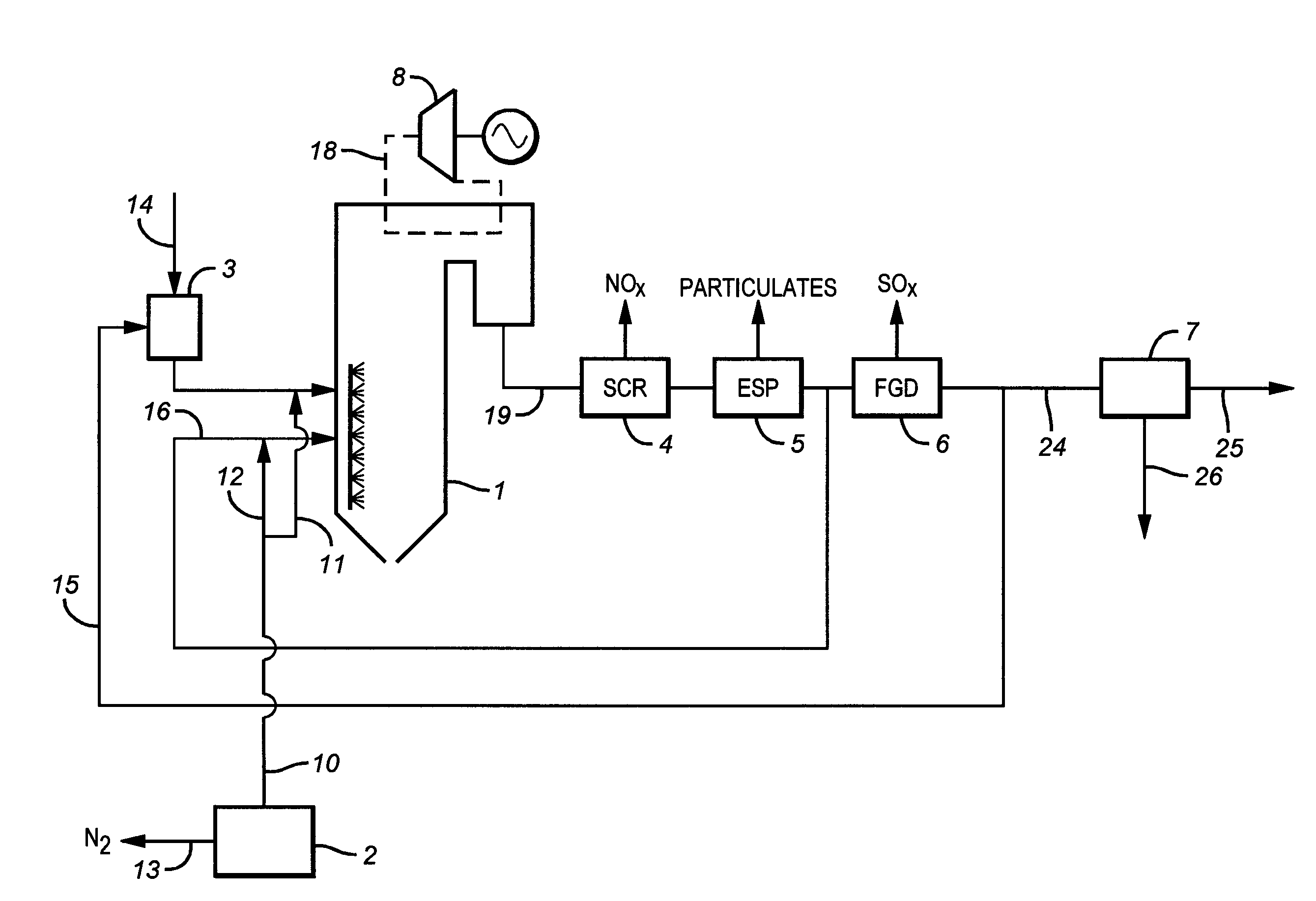
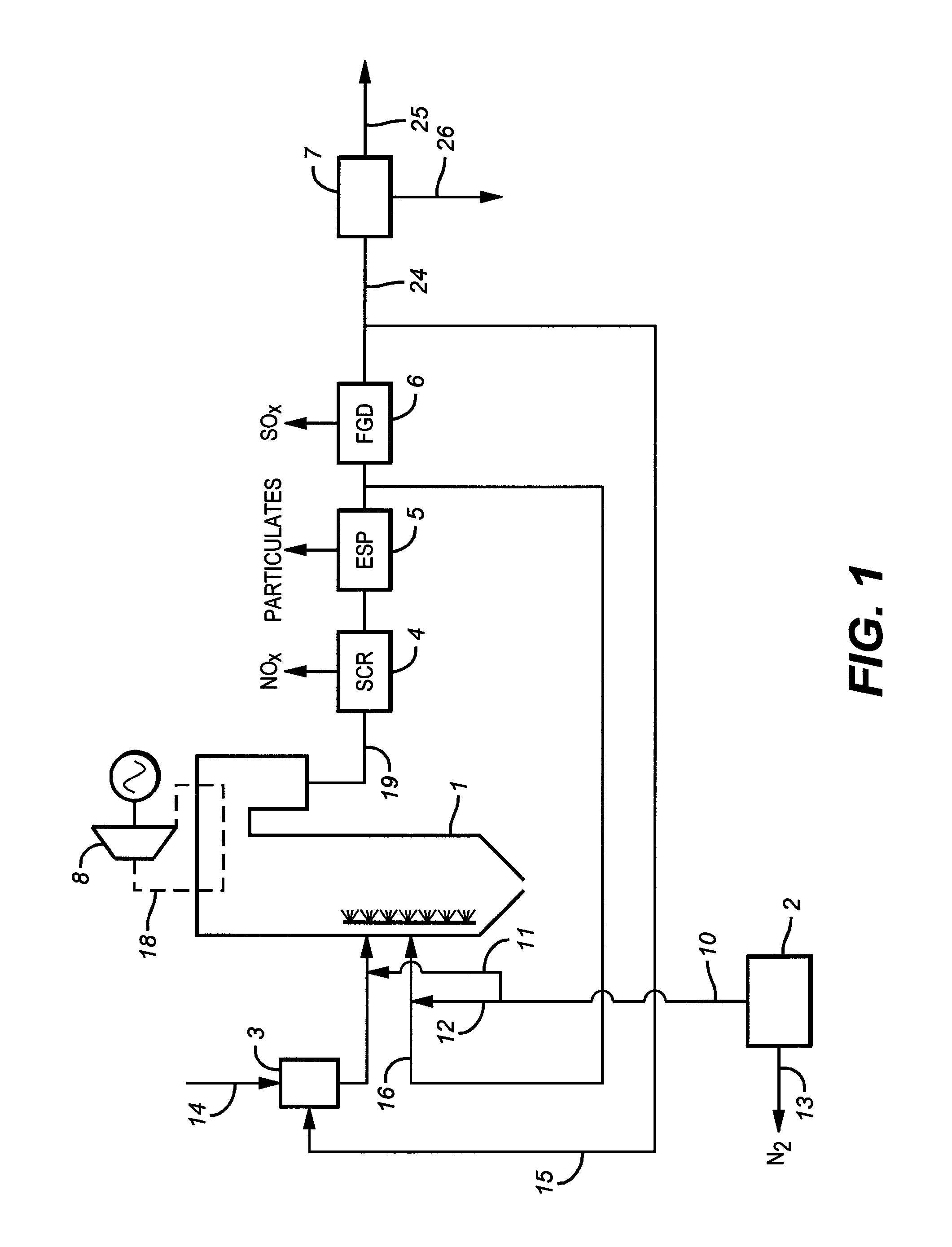
[0039]The invention will now be described in further detail with reference to the figures of which FIGS. 1, 2 and 3 show apparatuses according the invention, in varying degrees of detail, going from FIG. 1 which is the least detailed to FIG. 3 which is the most detailed. FIGS. 4 and 5 show heat exchange diagrams for the prior art and one of the exchangers of FIG. 3 respectively. FIG. 6 shows an alternative version of FIG. 3.

[0040]FIG. 1 is a schematic view of an oxycombustion plant. Air separation unit 2 produces an oxygen stream 10 at a typical purity of 95-98 mol. % and a waste nitrogen stream 13. Oxygen stream 10 is split into two sub streams 11 and 12. The primary flue gas recycle stream 15 passes through coal mills 3 where coal 14 is pulverized. Substream 11 is mixed with the recycle stream downstream of the coal mills 3 and the mixture is introduced in the burners of the boiler 1. Sub stream 12 is mixed with secondary flue gas recycle stream 16 which provides the additional ba...


PUM

PropertyMeasurementUnit
pressureaaaaaaaaaa
pressureaaaaaaaaaa
pressureaaaaaaaaaa

Abstract

A process for separating carbon dioxide from a compressed, dried and cooled carbon dioxide containing fluid comprises separating the fluid into at least a carbon dioxide enriched stream, and a carbon dioxide depleted stream, expanding at least part of the carbon dioxide lean stream in an expander, compressing a process stream wherein the power for the compression step is at least in part provided by the power generated by the expander.

Description

TECHNICAL FIELD[0001]The present invention relates to a process and apparatus for the separation of gaseous mixture containing carbon dioxide as main component. It relates in particular to processes and apparatus for purifying carbon dioxide, for example coming from combustion of a carbon containing fuel, such as takes place in an oxycombustion fossil fuel or biomass power plant.BACKGROUND ART[0002]The combustion of carbon containing fuels (biomass, waste, fossil fuels such as coal, lignite, hydrocarbons, . . . ) produces CO2 and gases, such as SO2, SO3, NOx, which pollute the atmosphere and are major contributors to the greenhouse effect especially CO2. These emissions of CO2 are concentrated in four main sectors: power generation, industrial processes, transportation, and residential and commercial buildings. The main application of CO2 capture is likely to be in power generation and large energy consuming industries, particularly cement, iron and steel and chemical production and...

Claims


Application Information

Patent Timeline
Patent Type & Authority Applications(United States)
IPC IPC(8): B01D19/00B01D3/14B01D53/00
CPCB01D53/002Y02E50/12B01D2256/22B01D2257/302B01D2257/404F23J15/006F23J2900/15061F25J3/0266F25J3/04521F25J3/04533F25J2200/02F25J2200/04F25J2200/70F25J2200/76F25J2205/04F25J2210/04F25J2210/70F25J2215/04F25J2220/82F25J2220/84F25J2230/08F25J2230/20F25J2230/30F25J2230/42F25J2240/90F25J2245/02F25J2260/80F25J2270/02Y02C10/12B01D53/74Y02E50/10Y02C20/40
Inventor DARDE, ARTHURHA, BAOTRANIER, JEAN-PIERRE
Owner AIR LIQUIDE PROCESS & CONSTRUCTION INC
Why Eureka
Try Eureka