Elastomeric Sealing Element for Gas Compressor Valve

a technology of gas compressor valve and sealing element, which is applied in the direction of machines/engines, liquid fuel engines, positive displacement liquid engines, etc., can solve the problems of reducing the ability of the valve to form a gas tight seal for extended periods of time, and affecting the service life of the compressor valve. , to achieve the effect of improving the service life of the compressor valve, reducing the potential of impact damage, and improving the sealing

Inactive Publication Date: 2009-01-15
DELAWARE CAPITAL FORMATION
View PDF9 Cites 12 Cited by
  • Summary
  • Abstract
  • Description
  • Claims
  • Application Information

AI Technical Summary

Benefits of technology

[0024]The use of elastomeric material as the sealing element of a reciprocating gas compressor valve has a number of benefits. One important benefit is a better gas tight seal within the reciprocating gas compressor. Elastomeric materials by their nature flex and conform to surfaces that they come into with. Hence, a second benefit is a durable, gas tight seal with irregularities in the seat surface. Another benefit is that the elastomeric material absorbs shock or the forces between the sealing element and the seat, reducing the potential of impact damage of either element and increasing the useful life of the compressor valve. The elastomeric material is also resilient so as to minimize the damage caused by entrained liquids or solid debris that may be in the gas stream. Time between reciprocating gas compressor valve failure is increased. Other benefits of the invention will become clear from the description of the invention.

Problems solved by technology
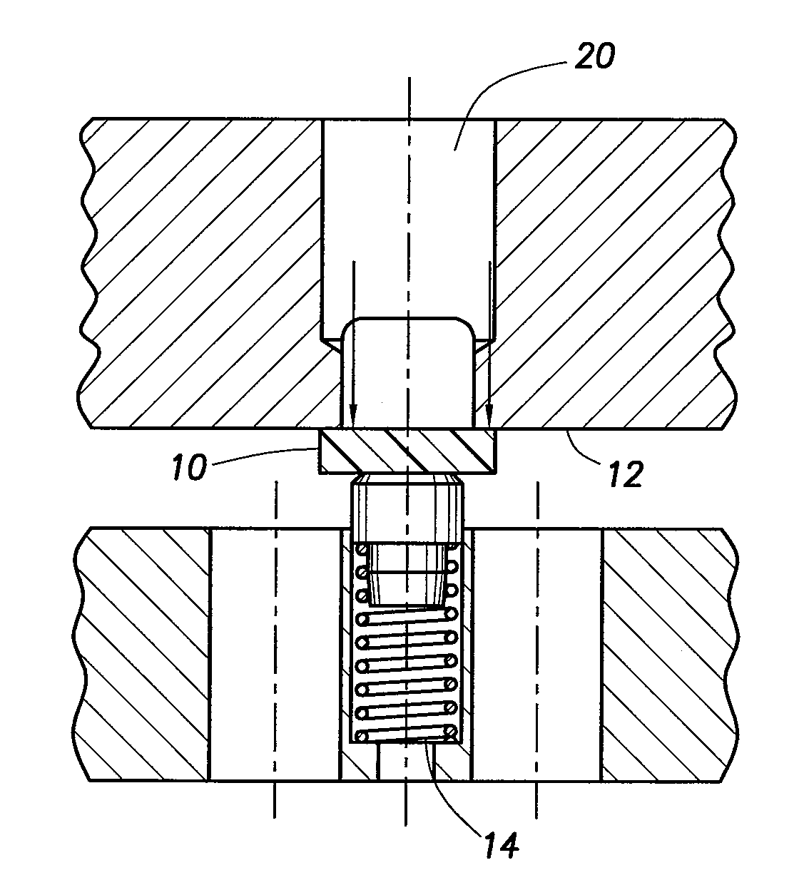
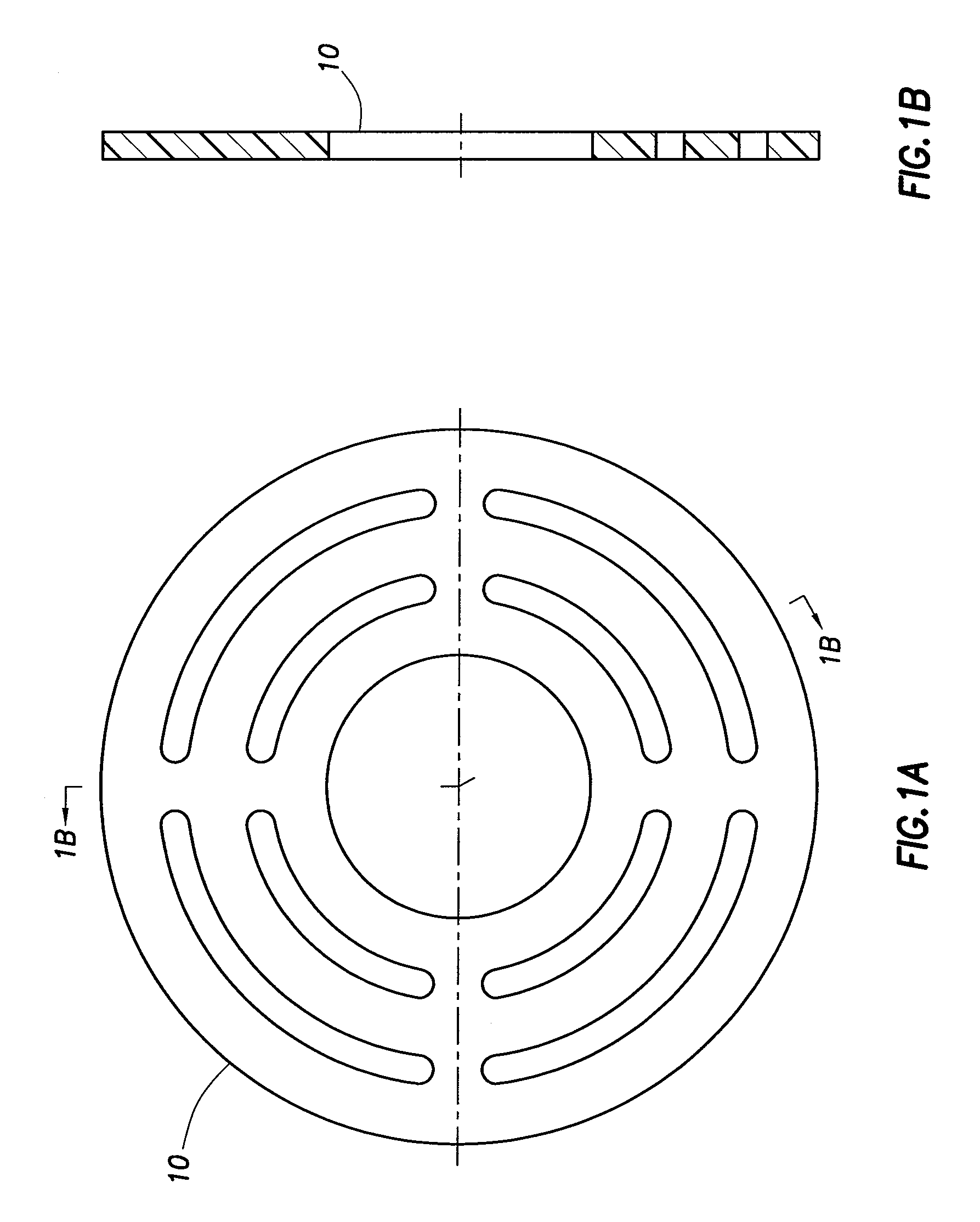
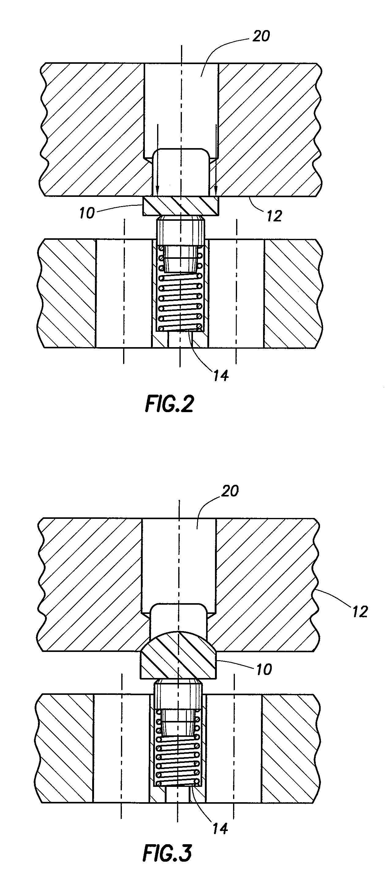
First, the inherent property of elastomers to flex and conform to irregular or damaged surfaces produces a gas tight seal over a variety of damaged or undamaged surfaces.
Sixth, elastomeric sealing elements are relatively easy to make and cost competitive.
Currently used non-resilient materials lack this property and the ability of the valve to form a gas tight seal for extended periods of time diminishes.
Furthermore, in spite of the variety of shapes, all current valve designs suffer from damage by entrained dirt and liquids in the gas stream and the accumulated wear of a large number of opening and closing events.

Method used


Image

  • Elastomeric Sealing Element for Gas Compressor Valve
  • Elastomeric Sealing Element for Gas Compressor Valve
  • Elastomeric Sealing Element for Gas Compressor Valve

Examples


example 1

[0099]As a first field test, a 1400 rpm Ariel reciprocating gas compressor was used in gas gathering service. This machine is desirable for testing the sealing element of the subject invention because of its rotating speed. A large number of opening and closing cycles may be accumulated in a short period of time. In this initial test, 90 durometer fluoro-elastomer, Mosites was applied to a nylon disk and used in a MOPPET® valve. The materials ran for six (6) days before failure occurred. Inspection of the parts indicated that the nylon base material melted and subsequent deformation of the parts and loss of seal, resulted in overheating and forced a shutdown of the compressor.

[0100]Nylon is no longer being used as a base material. PEEK has been applied as a result of its ability to operate at higher temperatures. The same elastomeric material, Mosites, was applied to the PEEK disks and the parts were run again. The parts ran for about 205 days before failure occurred. The standard p...

example 2

[0101]In the first test of the urethane material, the material failed in four (4) days and inspection revealed that the bond between the urethane and the PEEK material permitted the urethane to separate from the PEEK at discharge temperatures. In addition, the PEEK used in this test had been colored black by the addition of carbon which has the detrimental effect of making the thermoplastic material slippery. The MOPPET® valve parts were essentially undamaged but it was clear the bonding chemical between the urethane and the plastic allowed the urethane to separate. The suction valves were intact and in good condition because the suction temperatures are much lower than discharge temperatures. It seemed clear that the bonding agent had temperature limitations. Other bonding agents capable of withstanding higher temperatures must be utilized.

[0102]It should be noted that the standard valve (without the use of elastomeric material) began to overheat in only a few hours before having t...

example 3

[0103]In this example, the reciprocating gas compressor operated at a rather low compression ratio and the temperatures were low and the urethane sealing element applied to standard (non-black) PEEK ran continuously for over 100 days without problems. This provided the evidence that bonding materials are temperature sensitive. Adhesives and primers able to withstand higher temperatures and new radiused valve seats (surface vs. line contact) were installed. Compressor specifications were as follows:

Suction Pressure = 503 psiDischarge Pressure = 783 psiSuction Temperatures = 106° F.Discharge Temperatures = 169° F.Sealing ElementRPM = 327Travel = 0.120 inchesGas:75.5% HydrogenCompressor: Cooper JM-319.5% Methane 3.1% Ethane


PUM

PropertyMeasurementUnit
temperatureaaaaaaaaaa
elongationaaaaaaaaaa
piston speedsaaaaaaaaaa

Abstract

This invention relates to the use of elastomers with the sealing element of reciprocating gas compressor valves to increase the reliability of the gas tight seal within the reciprocating gas compressor valve and to increase the useful life of reciprocating gas compressor valve. The elastomeric material is either used as a coating layer on the sealing element of the reciprocating gas compressor valve, or as the entire sealing element. The elastomeric material acts as a cushion to reduce the wear on the sealing element, provides a superior gas tight seal, and is more tolerant of entrained dirt or liquids in the gas stream thereby increasing the operable life of the reciprocating gas compressor valve. Reducing the mean time between reciprocating gas compressor valve failures results in longer reciprocating gas compressor run times for the user, increased revenue generation for the user and safer operation of said equipment.

Description

CROSS REFERENCE TO RELATED APPLICATION[0001]The present application is a continuation of U.S. patent application Ser. No. 10 / 194,576, filed Jul. 12, 2002, which claims priority under Title 35, United States Code § 119 of U.S. Provisional Application Ser. No. 60 / 305,336, filed Jul. 13, 2001.TECHNICAL FIELD[0002]This invention relates to improved sealing and operational reliability of reciprocating gas compressor valves. More specifically, this invention is directed to the use of elastomeric material in connection with a sealing element of a reciprocating gas compressor valve to produce a reliable, durable seal.BACKGROUND OF THE INVENTION[0003]Reciprocating gas compressors are equipped with valves that open and close to intake and expel gases. Often such valves alternate open and close with each revolution of the compressor crankshaft and there are a very large number of suction and discharge events per minute. As a consequence, the valve must be designed to tolerate a high level of r...

Claims


Application Information

Patent Timeline
Patent Type & Authority Applications(United States)
IPC IPC(8): F16K1/46F04B53/10F16J15/32F04B39/00F04B39/08F04B39/10
CPCF04B39/08F04B39/1013F04B39/102F04B39/1033F05C2253/12F05C2225/00F05C2225/02F05C2225/04F05C2225/08F04B39/1053
Inventor DURHAM, KEVIN PATRICK
Owner DELAWARE CAPITAL FORMATION
Why Eureka
Try Eureka