
Method and apparatus for producing three-dimensional structure

a three-dimensional structure and apparatus technology, applied in the direction of manufacturing tools, circuit masks, laboratory glassware, etc., can solve the problems of inability to use nano-imprinting techniques, time and cost for manufacturing a minute die, and inability to meet the requirements of manufacturing, so as to achieve the effect of arbitrary three-dimensional structure and easy adaptation

Inactive Publication Date: 2009-01-15
PANASONIC CORP
View PDF5 Cites 19 Cited by
  • Summary
  • Abstract
  • Description
  • Claims
  • Application Information

AI Technical Summary

Benefits of technology

[0012]The inventors discovered that a three-dimensional structure in the desired shape can be produced by utilizing an inkjet printing technique or the like that uses a light irradiation mechanism to discharge droplets of a solution having a viscosity of 100 cps or lower in which polymer particles are dispersed. Specifically, the present invention is characterized in that droplets of a solution discharged from a nozzle are irradiated with light before coming in contact with a substrate, the solvent in the droplets is evaporated, and the polymer particles included in the droplets are melted to increase the viscosity. The present invention is based on the knowledge that the desired three-dimensional structure can be produced by bringing the viscosity-enhanced droplets into contact with the substrate, fixing the droplets to the substrate, and continuously depositing droplets to build up a solid object.

Problems solved by technology

Fabrication of a minute die requires time and cost, and is also technically difficult.
Furthermore, numerous varieties of dies must be fabricated for device prototypes having a large number of design modifications, or for limited production of diversified products, and it is therefore sometimes inappropriate to use a nano-imprinting technique.
Therefore, it is difficult to separate the die with high accuracy without collapsing the microasperity of the produced three-dimensional structure having a high aspect ratio.
For example, it is sometimes extremely difficult to form a nanopillar whose aspect ratio is 3 or higher using the nano-imprinting technique.
However, the material sprayed from the inkjet nozzles is limited to a low viscosity (about 1 to 10 cps, for example).
The discharged material disperses on the substrate after coming into contact with the substrate, and therefore the discharged material cannot be deposited, and a shape having a high aspect ratio is difficult to form.
This technique therefore cannot be utilized to produce three-dimensional structures such as nanopillars and micropillars.

Method used


Image

  • Method and apparatus for producing three-dimensional structure
  • Method and apparatus for producing three-dimensional structure
  • Method and apparatus for producing three-dimensional structure

Examples


embodiment 1

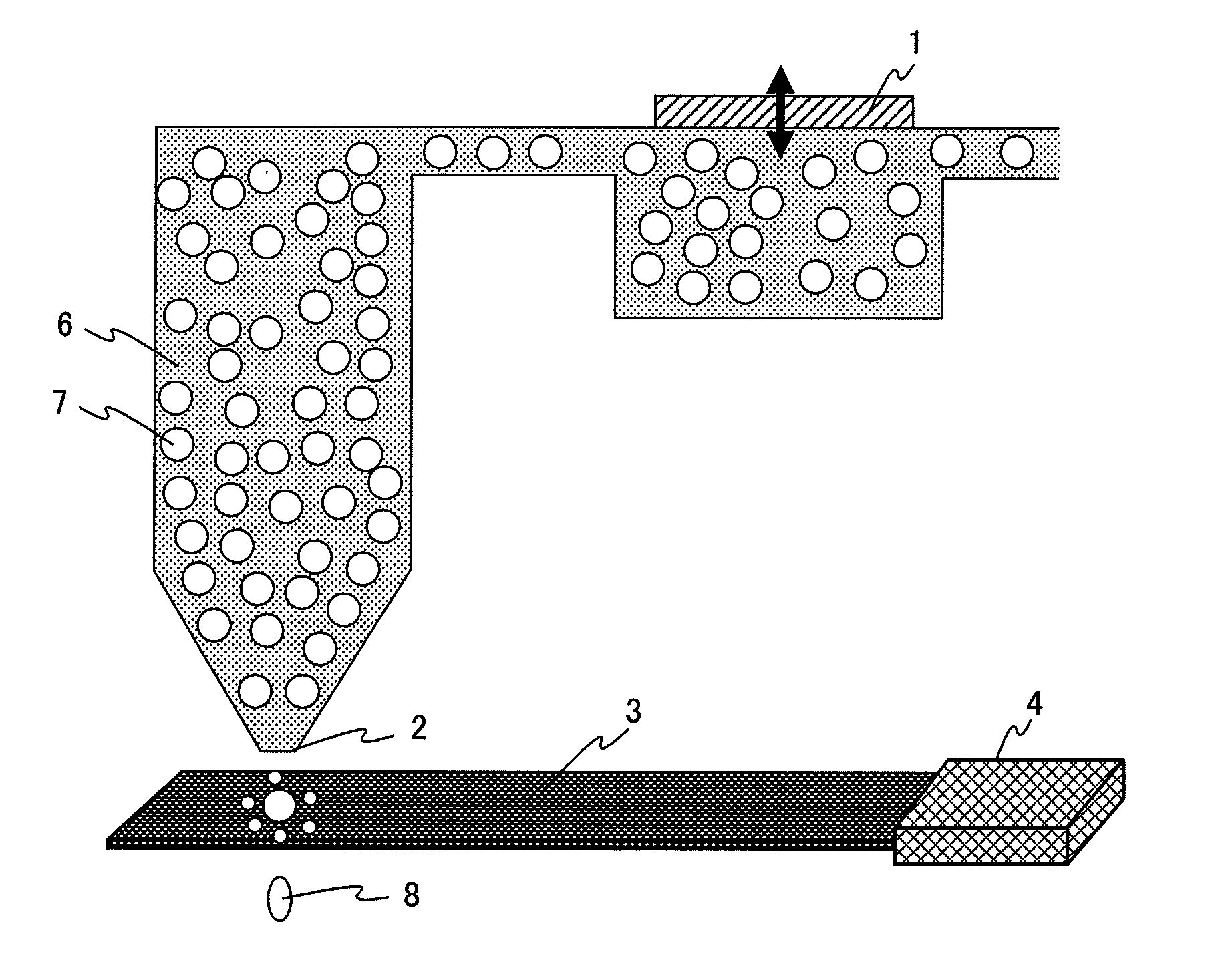
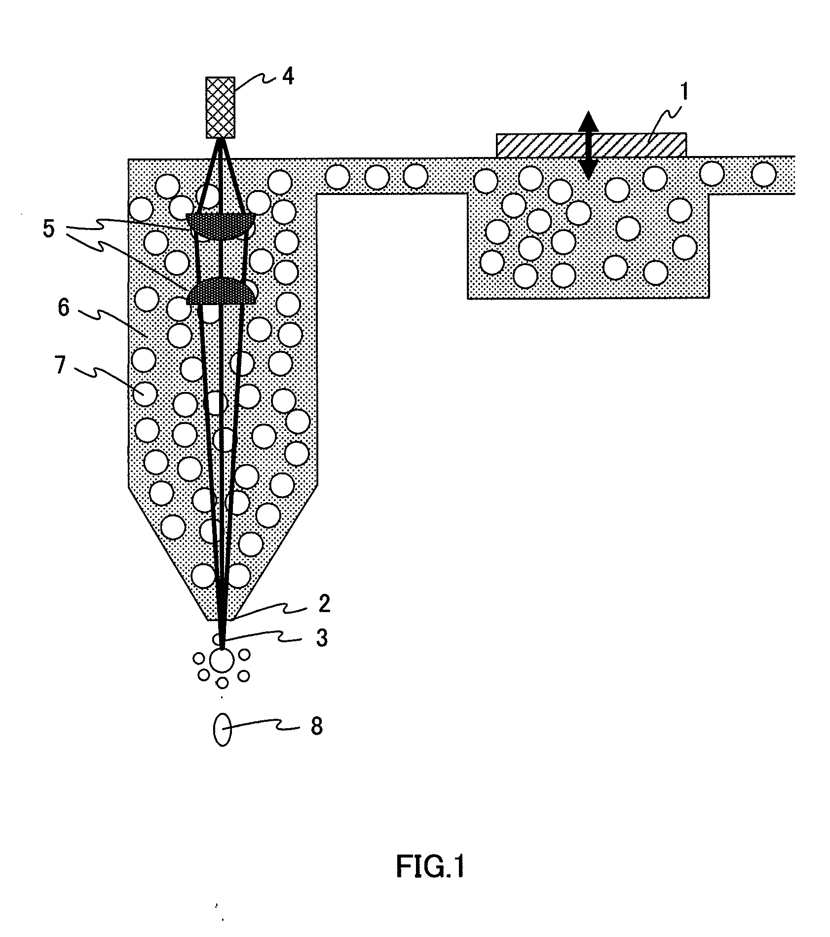
[0057]FIG. 1 shows an example of the inkjet head that is a component of the apparatus for producing a three-dimensional structure. The reference numeral 1 indicates a piezoelectric element, 2 indicates a nozzle, 3 indicates laser light, 4 indicates a laser, 5 indicates a lens, 6 indicates a solvent, 7 indicates a polymer particle, and 8 indicates a high-viscosity droplet.

[0058]Piezoelectric element 1 vibrates at high speed, and thereby solvent 6 and polymer particle 7 are discharged in the form of a droplet from nozzle 2. Laser light 3 is emitted from laser 4 (for example, YAG laser, semiconductor laser, and ultra violet laser). Laser light 3 passes through lens 5 and changes to collimated light, and the focal point of laser light 3 converted to collimated light is caused to coincide with the discharged droplet.

[0059]The discharged droplet is heated by the condensed laser light, the solvent is evaporated, and the polymer particle included in the droplet is melted. The droplet is the...

embodiment 2

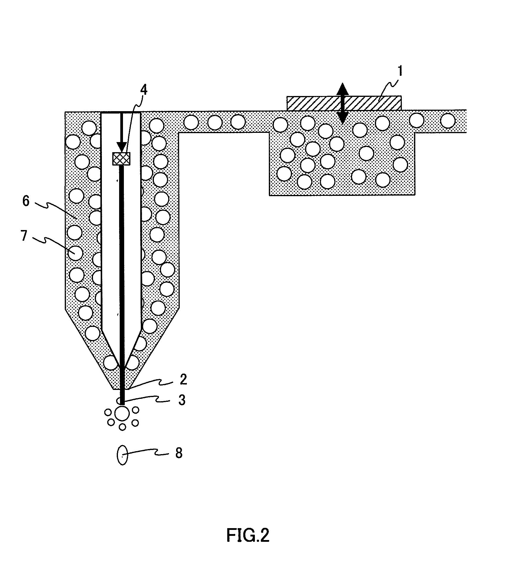
[0062]FIG. 2 shows another example of the inkjet head that is a component of the apparatus for producing a three-dimensional structure. In FIG. 2, components that are the same as those in FIG. 1 will be assigned the same reference numerals without further explanations.

[0063]A droplet of a solution that includes polymer particle 7 described above is discharged through the high-speed vibration of piezoelectric element 1 placed at an inkjet head. Laser 4 is mounted inside a cylinder placed in the center of the inkjet head. The cylinder is configured so that the solution cannot enter into the cylinder.

[0064]Gas may be released from the cylinder provided inside the inkjet in order to accelerate discharge of the solution. The gas may also be heated in order to change the viscosity of the discharged droplet.

[0065]When the discharged droplet is irradiated with laser light 3, the solvent (water, for example) is evaporated, the polymer particle included in the droplet is heated, and the polym...

embodiment 3

[0067]FIGS. 3 and 4 show other examples of the inkjet head unit that is an apparatus for producing a three-dimensional structure according to the present invention. In FIGS. 3 and 4, components that are the same as those in FIG. 1 will be assigned the same reference numerals without further explanations.

[0068]A droplet of a solution that includes polymer particle 7 previously described can be discharged by making piezoelectric element 1 inside the inkjet vibrate at high speed. Laser 4 is mounted outside the inkjet head. The laser is mounted substantially horizontal to the nozzle in FIG. 3, and above the nozzle at an angle in FIG. 4. The discharged polymer particles are easily irradiated when laser light 3 is planar as shown in the drawing.

[0069]At this time, the laser light may be condensed and the droplet including the polymer particle may be irradiated from the side. When the discharged droplet is irradiated with laser light 3, the solvent water is evaporated, and the polymer part...


PUM

PropertyMeasurementUnit
Particle sizeaaaaaaaaaa
Structureaaaaaaaaaa
Viscosityaaaaaaaaaa

Abstract

The present invention aims to produce a three-dimensional structure having a high aspect ratio by using inkjet printing techniques or the like. Specifically, a three-dimensional structure is produced by ejecting a liquid drop of a solution, which contains a solvent and polymer particles dispersed in the solvent while having a viscosity of not more than 100 cps, from a nozzle onto a substrate; then evaporating the solvent and melting the polymer particles by irradiating the liquid drop with light; and then depositing the molten polymer particles on the substrate. The present invention can be applied to production of biochips and the like.

Description

TECHNICAL FIELD[0001]The present invention relates to a method and apparatus for producing a three-dimensional structure.[0002]The present invention is characterized in using an inkjet printing technique or the like in which a light irradiation mechanism is used to spray droplets that include polymer particles.BACKGROUND ART[0003]The development of biosensor devices such as DNA chips and immune analysis chips has been proceeded for the purposes of separating and detecting various components in blood that include glucose and the like, or for separating DNA (deoxyribonucleic acid) components. A pillar having a diameter on the nano meter or micro meter level and a height of several hundred micrometers is formed in these devices. Accordingly, a technique for forming a three-dimensional structure (including a nanopillar or a micropillar) having a high aspect ratio is essential to the fabrication of such a device.[0004]In the conventional technique for forming a three-dimensional structur...

Claims


Application Information

Patent Timeline
IPC IPC(8): B29C41/08B05B13/02B81C99/00
CPCB01J19/0046B41M7/009B01J2219/00527B01J2219/00585B01J2219/00596B01J2219/00644B01J2219/00711B01L3/502707B29C67/0059B41M3/006B81B2203/0361B81C1/0046B81C99/0095B82Y30/00H05K3/0079H05K2203/013B41M7/0081B01J2219/00378B29C64/112B29C67/00B81C99/00B05C5/00B05C9/12
Inventor NAGAI, HISAOYOSHIDA, HIDEHIROFURUKAWA, TAKAYUKIINOUE, TAKASHI
Owner PANASONIC CORP
Learn More