
Building window having a visible-light-reflective optical interference coating thereon

Active Publication Date: 2009-01-15
RAYTHEON CANADA LTD
View PDF26 Cites 13 Cited by
  • Summary
  • Abstract
  • Description
  • Claims
  • Application Information

AI Technical Summary

Benefits of technology

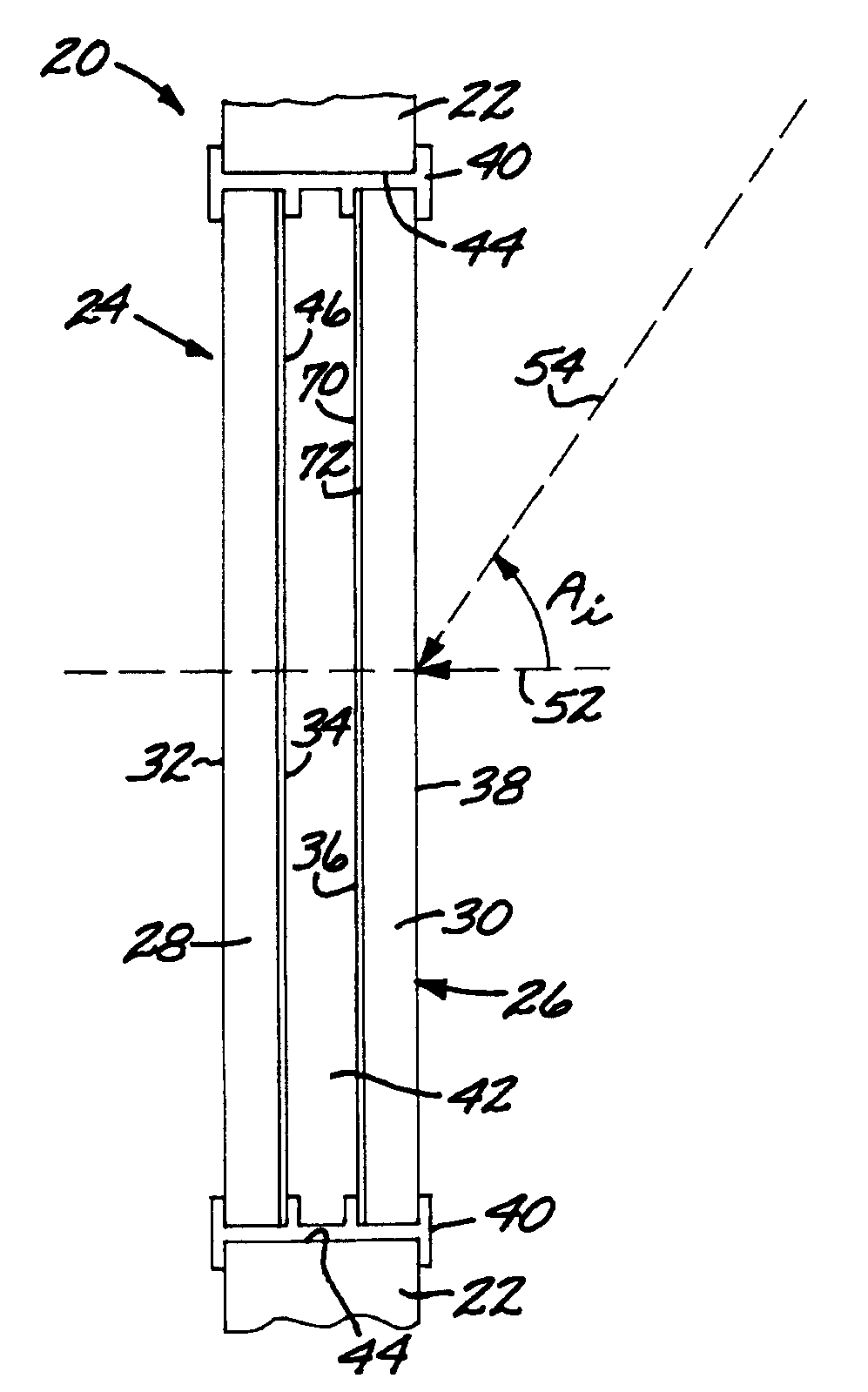
[0010]The window may have two or more panes of glass. For example, the building transparent window glazing may comprise two panes of glass set into a building window frame with a dead space between the panes of glass. The dead space may be filled with air or an inert gas, or may be evacuated. The dead space between the two panes of glass reduces heat transfer through the window by conduction and convection mechanisms, thereby providing insulation. The first surface is on one of the two panes of glass, most preferably on one of the surfaces facing the dead space.
[0011]One of the desirable features of the present approach is that it may be used in conjunction with an infrared-reduction coating overlying (and optionally but preferably contacting) a second surface (which may be the same as the first surface, but is preferably a different surface) of the building transparent window glazing. In the case of the two-pane glazing, the optical interference coating and the infrared-reduction coating may be on the two surfaces facing the dead space. This arrangement prevents the coatings from being damaged from sources exterior to the building or interior to the building.
[0012]The basis of the present approach is the recognition that the visible-light portion of the solar spectrum carries nearly as much heat energy as does the infrared-light portion of the solar spectrum. Prior approaches that have emphasized only the reduction of infrared energy that would otherwise pass through the window into the building, such as those using ITO coatings on the window, have had little or no effect on the heat energy transmitted with the visible light. Prior approaches that have reduced the visible light, such as tints on the window, have reduced the visibility through the window of the occupants of the building in the direction normally viewed, which is roughly in the plane of the horizon and a few degrees above and below the horizontal plane.
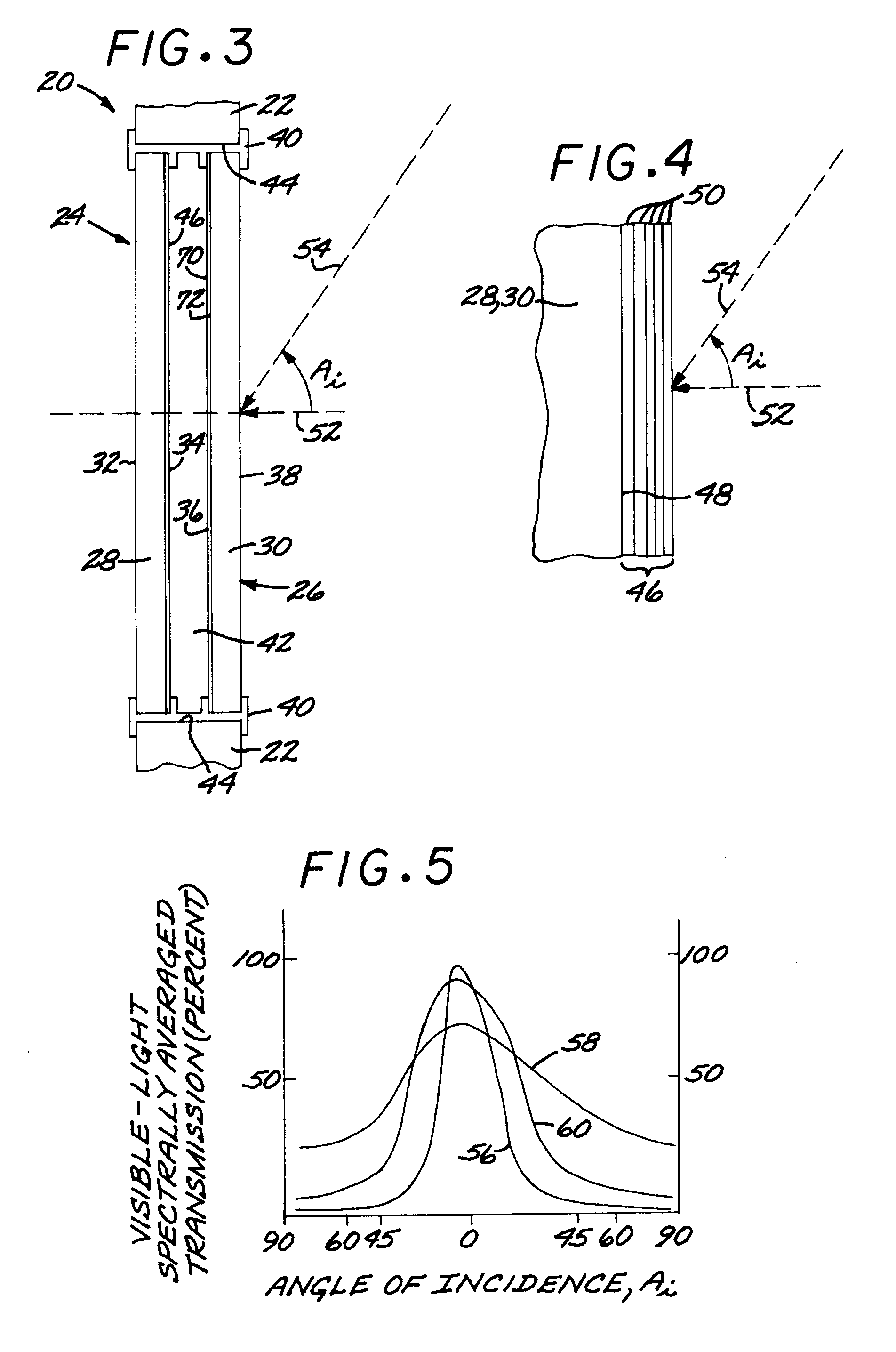
[0014]The present approach that attenuates visible light at higher angles of incidence may be combined with other non-directional techniques that reduce the penetration of infrared wavelengths through the window into the building, thereby addressing the wavelength ranges that carry about 95 percent of the heat energy in solar radiation. For example, the window may be tinted, although tinting reduces visibility over all angles, including 0-degree and near-0-degree angles of incidence.
[0016]One advantage of the present approach is that it is highly flexible. The windows of a building may be given different treatments according to the nature of the scene viewed through the window and other considerations. For example, a window having little by way of a scenic view for the occupant can be given a highly effective coating and insulating treatment over its entire surface. In a case where the view is highly desirable in a particular direction, the attenuation afforded by the optical interference coating may be tailored to provide little loss of visibility in the direction of the desirable view. The optical interference coating may be intentionally spatially varied to be non-uniform over the surface of the widow. One such technique is to coat only a portion of the window with the optical interference coating, so that there is no loss of view at all through the uncoated portion (although there will be a higher heat transmission through this uncoated portion), while other portions of the window are provided with the optical interference coating. (Spatial variation of the optical interference coating includes, but is not limited to, an absence of the optical interference coating in some areas and its presence in other areas.) For example, the window could be coated on its upper portion and / or lower portion, but left uncoated in a band from 4-7 feet from floor level. The present approach may also be used to grade or graduate the transmission of the optical interference coating, so that different areas have different attenuations for the same higher angle of incidence.
[0017]The multilayer dielectric inorganic optical interference coating thus functions to some degree in the manner of an exterior window shade or awning by reducing the intensity of the visible sunlight at higher angles of incidence. The present approach differs in visual effect from the exterior window shade or awning in that features at the higher angles of incidence may be seen more darkly than those at lower angles of incidence, and also in that the present approach has no window shade or awning projecting from the side of the building.

Problems solved by technology

In summer, such interior heating of the building increases the air conditioning demand, and thence the consumption of electrical power.
These shades and awnings are highly effective in controlling interior heat loading, but reduce the visibility through the windows.
Exterior window shades and awnings can be used on residences and other smaller buildings, but they cannot be used effectively in high-rise buildings.
Because the human eye sees only in the visible spectrum, “low E” window coatings have been designed to block the infrared portion of sunlight, allowing the visible portion of the sunlight to enter the window largely unimpeded.
These techniques have been only partially effective for high-rise and other buildings for which exterior window shades and awnings cannot be used.

Method used


Image

  • Building window having a visible-light-reflective optical interference coating thereon
  • Building window having a visible-light-reflective optical interference coating thereon
  • Building window having a visible-light-reflective optical interference coating thereon

Examples


Embodiment Construction

[0028]FIG. 1 depicts a building structure 20. The building structure 20 includes a building external wall 22 in which a plurality of windows 24 are set so that the occupants of the building structure 20 may see out and sunlight may enter the interior of the building structure 20.

[0029]FIGS. 2-3 illustrate the structure of the windows 24 in greater detail. A window 24 in accordance with the present approach includes a building transparent window glazing 26. (As used herein, a “building transparent window glazing” is a sheet of glass made to be set into a frame to form a window of a building.) The building transparent window glazing 26 includes at least one, and in a typical case as illustrated, two panes 28, 30 of a material that is transparent to visible light. (As used herein, “visible light” is light of a wavelength of 425-675 nanometers, although the human eye normally has some sensitivity to light of wavelengths outside this range.) The material that is transparent to visible li...


PUM


Abstract

A building structure includes a building transparent window glazing, and an optical interference coating overlying and contacting a first surface of the building transparent window glazing. A spectrally averaged transmission of visible light through the building transparent window glazing with the optical interference coating thereon is smaller at a higher angle of incidence than at a lower angle of incidence.

Description

[0001]This invention relates to a building window, and more particularly to a building window having a multilayer interference coating thereon that reduces transmittance of visible light at high angles of incidence.BACKGROUND OF THE INVENTION[0002]Windows form a large portion of the exterior surface area of many buildings. When light enters the building through the windows, the interior is heated by the light energy. In summer, such interior heating of the building increases the air conditioning demand, and thence the consumption of electrical power.[0003]A number of techniques have been proposed to control the heating of the interior of the building by the light entering the windows. One commonly used approach is exterior window shades and awnings that block all wavelengths of the sunlight incident at higher angles, but allow a person in the building to look out through the window at normal and near-normal incidence angles (measured in the vertical plane) to the window. These shade...

Claims


Application Information

Patent Timeline
IPC IPC(8): G02B1/10E06B3/24
CPCE06B9/24G02B5/281E06B2009/2417E06B2009/2405
Inventor MITCHELL, DANIEL B.
Owner RAYTHEON CANADA LTD
Features
  • Generate Ideas
  • Intellectual Property
  • Life Sciences
  • Materials
  • Tech Scout
  • Unparalleled Data Quality
  • Higher Quality Content
  • 60% Fewer Hallucinations
Learn More