Method and system for high resolution, ultra fast 3-d imaging

a high-resolution, ultra-fast technology, applied in the field of high-resolution, ultra-fast 3d imaging, can solve the problems of difficult detection of the orientation of the young's fringes, large processing of the images in hardware or software, and inaccurate techniques, and achieves simple alignment procedures and high rates

Inactive Publication Date: 2009-01-15
MASSACHUSETTS INST OF TECH
View PDF22 Cites 151 Cited by
  • Summary
  • Abstract
  • Description
  • Claims
  • Application Information

AI Technical Summary

Benefits of technology

[0007]Accordingly, a high-speed three-dimensional imaging system, based on projecting light onto an object and imaging the reflected light from multiple angles, includes a single lens camera subsystem with an active imaging element and CCD element, and a correlation processing subsystem. The active imaging element can be a rotating aperture which allows adjustable non-equilateral spacing between defocused images to achieve greater depth of field and higher sub-pixel displacement accuracy.
[0008]The correlation processing subsystem achieves high resolution, ultra fast processing. This processing can include recursively correlating image pairs down to diffraction limited image size of the optics. Correlation errors are eliminated during processing by a technique based on the multiplication of correlation table elements from one or more adjacent regions. Processing is accomplished by compressing the images into a sparse array format before they are correlated.
[0010]The present system and method circumvent many of the inherent limitations of multi-camera systems that use fast Fourier transform (FFT) spectral based correlation. Another advantage of the present approach is that it uses a single optical axis resulting in very simple aligning procedures. Problems associated with the motion (vibration) of cameras with respect to each other that are found in stereoscopic techniques and that would otherwise produce erroneous results are also eliminated.
[0011]The present method and apparatus can be used for such applications as near real-time parts inspection, surface mapping, bio-measurement, object recognition, and part duplication, and makes feasible a myriad of technologies that are currently hindered by the inability to resolve three-dimensional information at high rates.

Problems solved by technology

These techniques, although accurate, require extensive processing of the images in hardware or software.
In practice, however, it has been found that it is difficult to detect the orientation of the Young's fringes.

Method used


Image

  • Method and system for high resolution, ultra fast 3-d imaging
  • Method and system for high resolution, ultra fast 3-d imaging
  • Method and system for high resolution, ultra fast 3-d imaging

Examples


Embodiment Construction

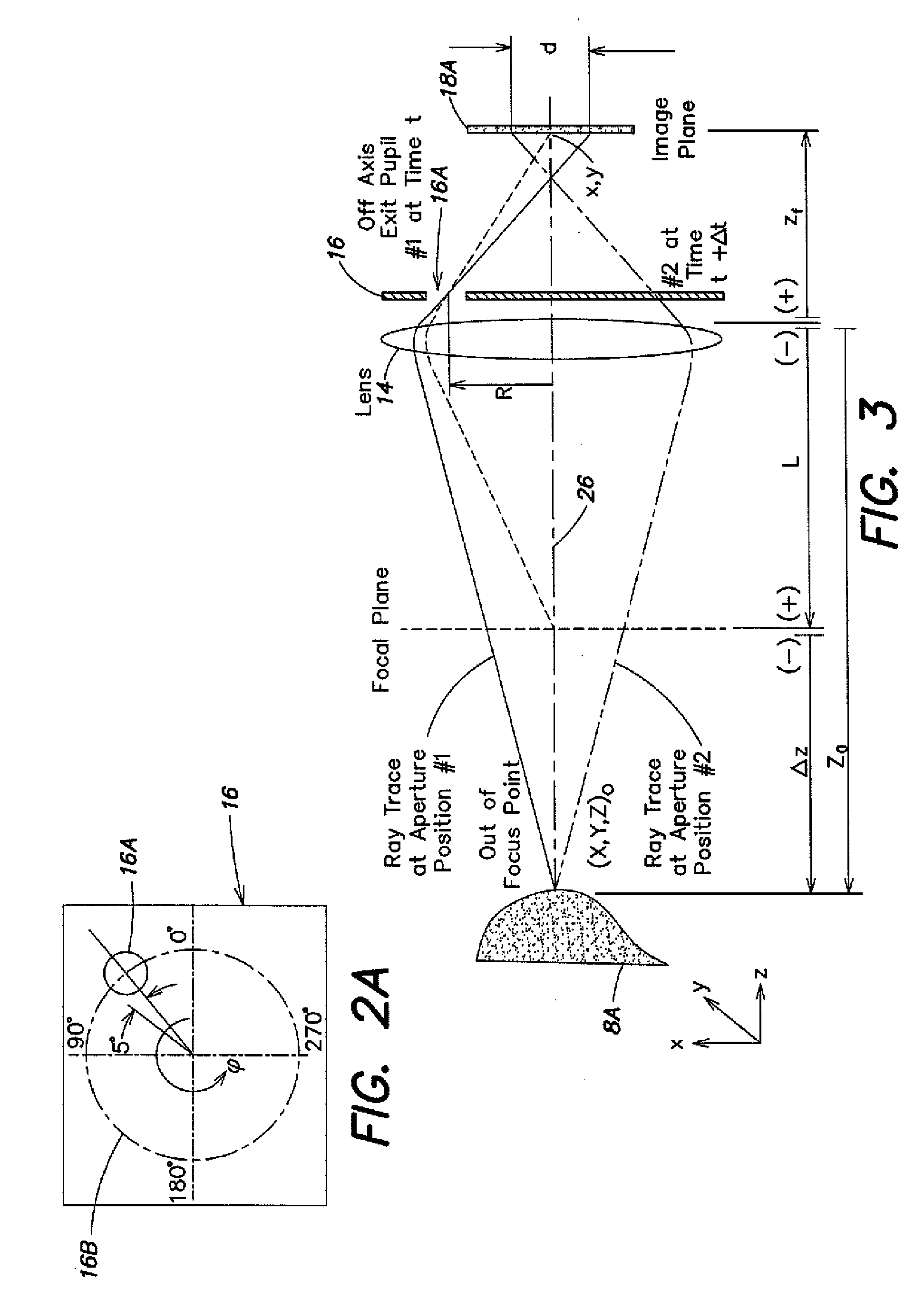
[0021]The present system uses image correlation which provides ultra fast and super high resolution image processing. The image processing includes a technique referred to as sparse array image correlation. Although this processing offers several advantages on multi-exposed single frame images, it is particularly suitable for processing single exposed image frames. The system includes a single lens, single camera subsystem that in an embodiment uses a rotating off-axis aperture for sampling defocused images and generating single exposed frames with depth related image disparity between them.

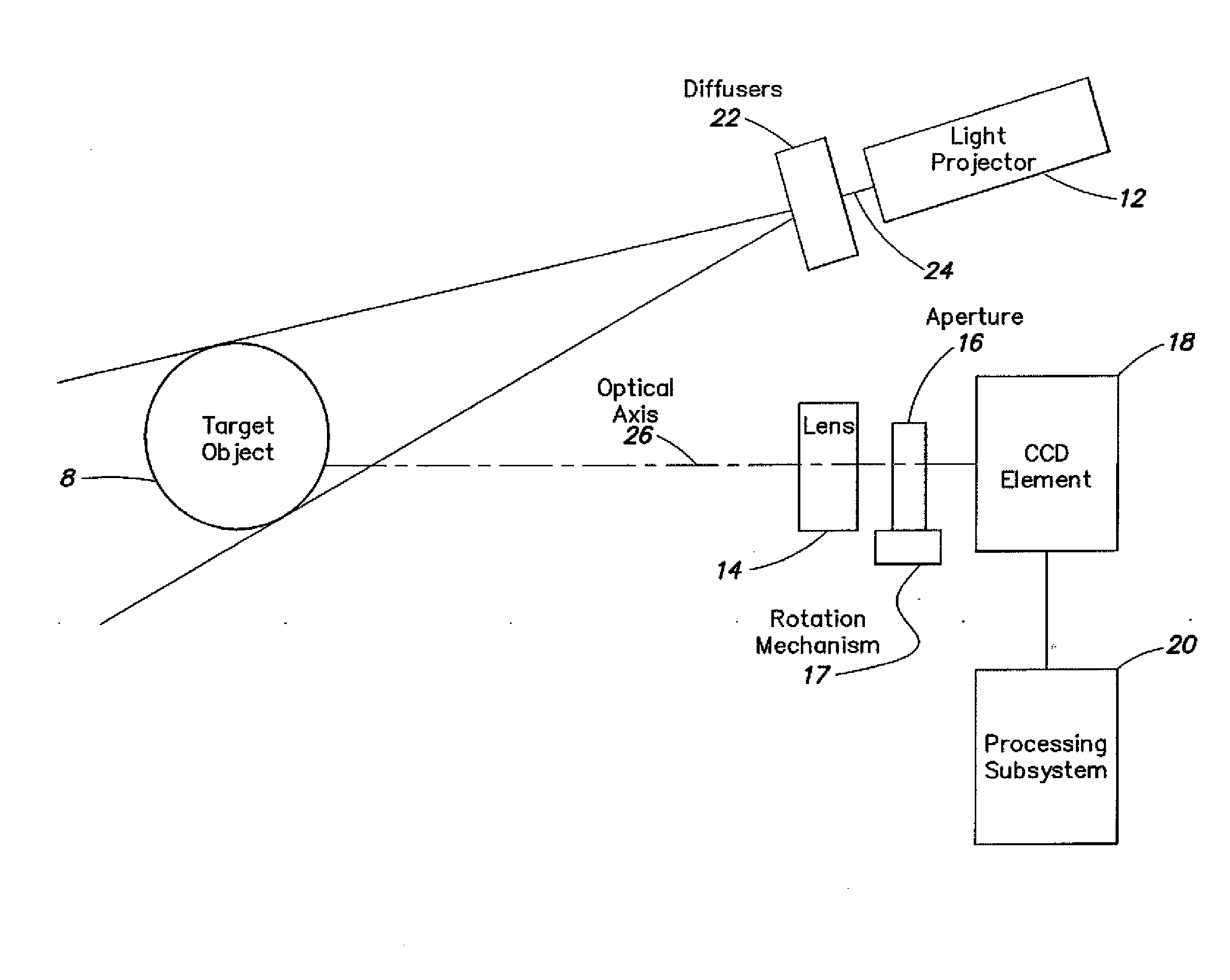
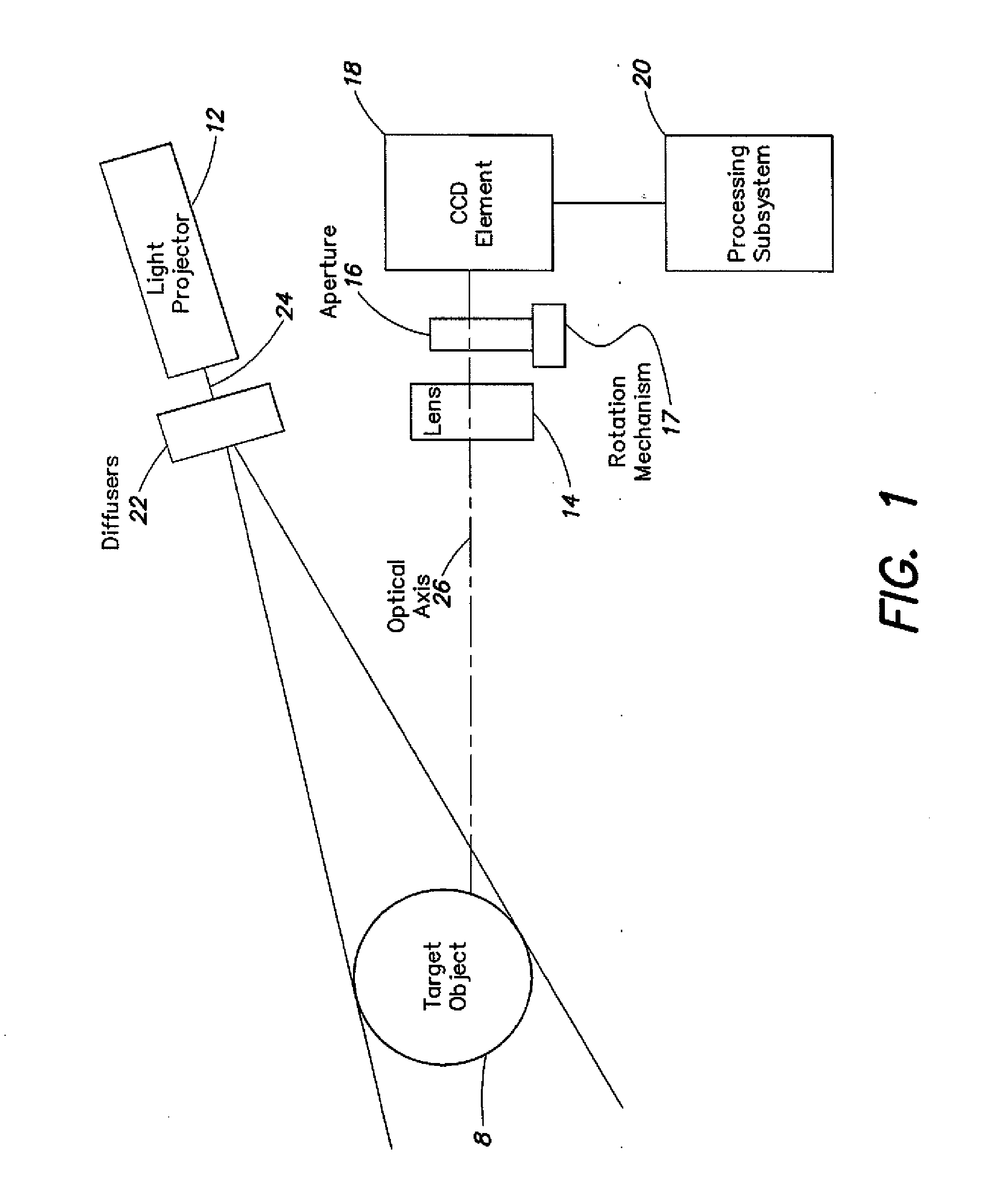
[0022]FIG. 1 illustrates an embodiment of a 3-D imaging system which includes a light projector 12, a camera subsystem that codes three-dimensional position information into two-dimensional images using a lens 14, a rotating aperture 16, rotation mechanism 17 and a CCD element 18 aligned along an optical axis 26. The imaging system further includes a correlation processing subsystem 20 that is co...


PUM

PropertyMeasurementUnit
diffuser angleaaaaaaaaaa
dimensionsaaaaaaaaaa

Abstract

A high-speed three-dimensional imaging system includes a single lens camera subsystem with an active imaging element and CCD element, and a correlation processing subsystem. The active imaging element can be a rotating aperture which allows adjustable non-equilateral spacing between defocused images to achieve greater depth of field and higher sub-pixel displacement accuracy. A speckle pattern is projected onto an object and images of the resulting pattern are acquired from multiple angles. The images are locally cross-correlated using a sparse array image correlation technique and the surface is resolved by using relative camera position information to calculate the three-dimensional coordinates of each locally correlated region. Increased resolution and accuracy are provided by recursively correlating the images down to the level of individual points of light and using the Gaussian nature of the projected speckle pattern to determine subpixel displacement between images. Processing is done at very high-speeds by compressing the images before they are correlated. Correlation errors are eliminated during processing by a technique based on the multiplication of correlation table elements from one or more adjacent regions.

Description

RELATED APPLICATIONS[0001]This application is a continuation of U.S. Ser. No. 11 / 725,585, filed Mar. 19, 2007, which is a continuation of U.S. Ser. No. 09 / 616,606, filed on Jul. 14, 2000, both entitled “METHOD AND SYSTEM FOR HIGH RESOLUTION, ULTRA FAST 3-D IMAGING, and both of which are hereby incorporated by reference herein in their entirety.BACKGROUND OF THE INVENTION[0002]Devices which rely on machine vision such as robotic and manufacturing equipment, image based measurement equipment, topographical mapping equipment, and image recognition systems often use correlation of a single image (auto-correlation) or correlation between multiple images (cross-correlation) to establish the size, shape, speed, acceleration and / or position of one or more objects within a field of view.[0003]Image correlation is typically performed using Fast Fourier Transforms (FFTs), image shifting, or optical transformation techniques. These techniques, although accurate, require extensive processing of ...

Claims


Application Information

Patent Timeline
Patent Type & Authority Applications(United States)
IPC IPC(8): G06K9/64H04N5/225G03C9/08
CPCG06T7/0057G01B11/2545G06T7/521
Inventor HART, DOUGLAS P.
Owner MASSACHUSETTS INST OF TECH
Why Eureka
Try Eureka