
Method of manufacturing micro electro mechanical systems device

a technology of electromechanical systems and manufacturing methods, which is applied in the direction of generators/motors, acceleration measurement using interia forces, instruments, etc., can solve the problems of deterioration in manufacturing yield, deterioration in performance, and deterioration in resonance frequency of sensors and unwanted modes

Inactive Publication Date: 2009-01-15
HITACHI LTD
View PDF8 Cites 68 Cited by
  • Summary
  • Abstract
  • Description
  • Claims
  • Application Information

AI Technical Summary

Benefits of technology

[0011]An object of the present invention is to provide a MEMS device which is robust to the misalignment and does not require the double-side wafer processing in the manufacture of a MEMS device such as an angular velocity sensor, an acceleration sensor, a combined sensor (sensor in which an angular velocity sensor and an acceleration sensor are integrated together), or a micromirror.
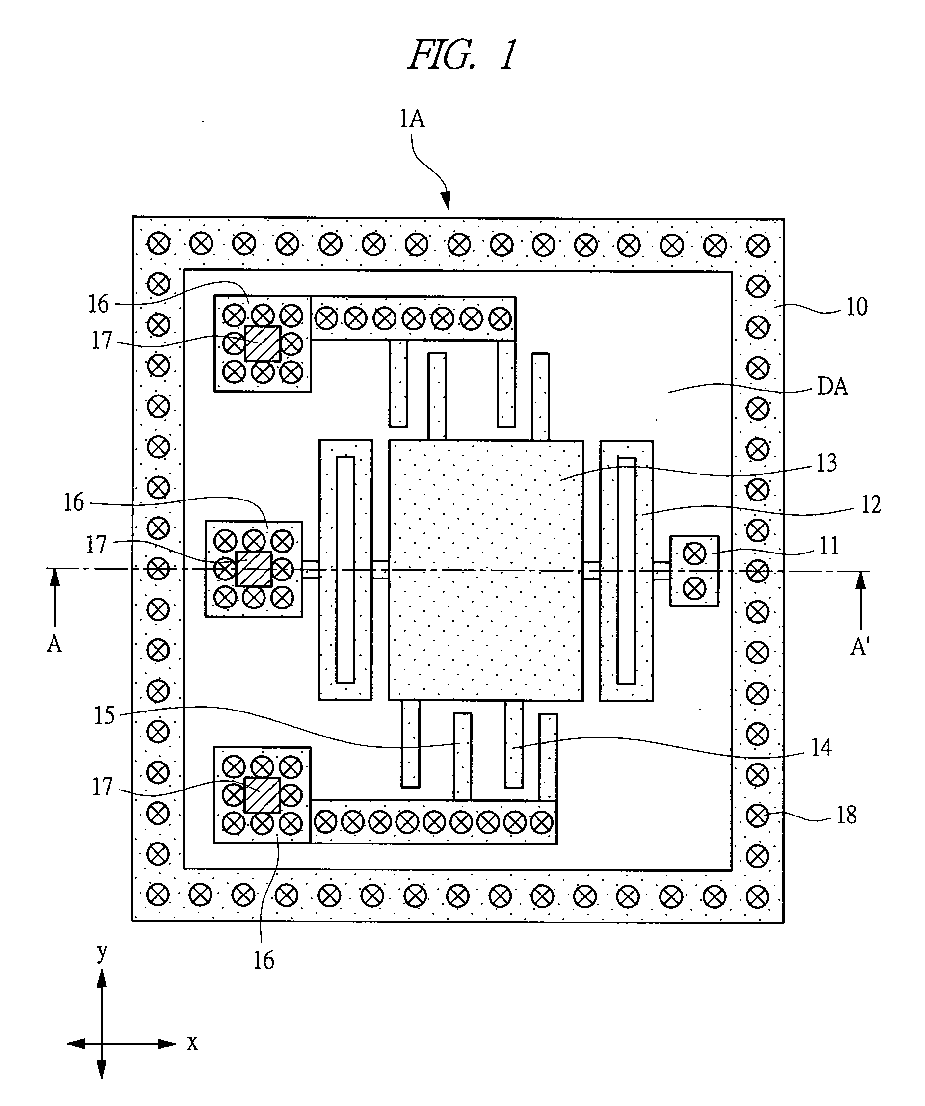
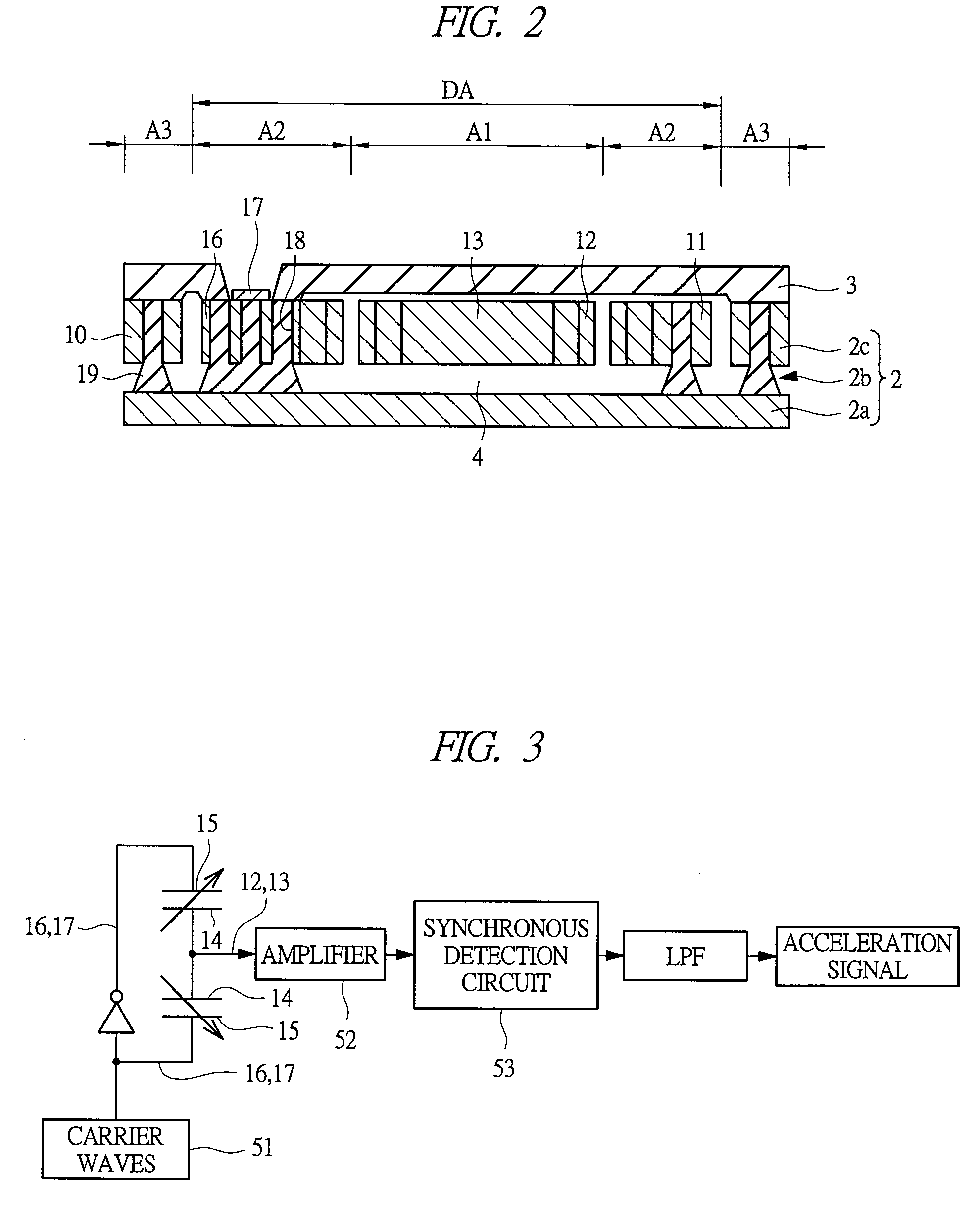
[0016]According to the method of manufacturing a MEMS device of the present invention, a substrate having a space formed therein is used, micro-holes are formed at necessary portions, and the holes are filled with a fixing material to fix surrounding portions of the holes to the supporting member. Therefore, different from the technology described in the Patent Document 1, the double-side processing for the wafer is not required. Also, since it is not required to know in advance the position where the fixing portion is to be placed when forming the space, a large amount of standard substrates (wafers) having a space can be produced. Furthermore, since a movable portion and a fixing portion are formed after the substrate (wafer) formed of a conductor and the substrate (wafer) to be a supporting member are bonded together, highly accurate alignment is not required. As a result, high-performance and highly reliable MEMS devices with little individual difference between devices can be manufactured.

Problems solved by technology

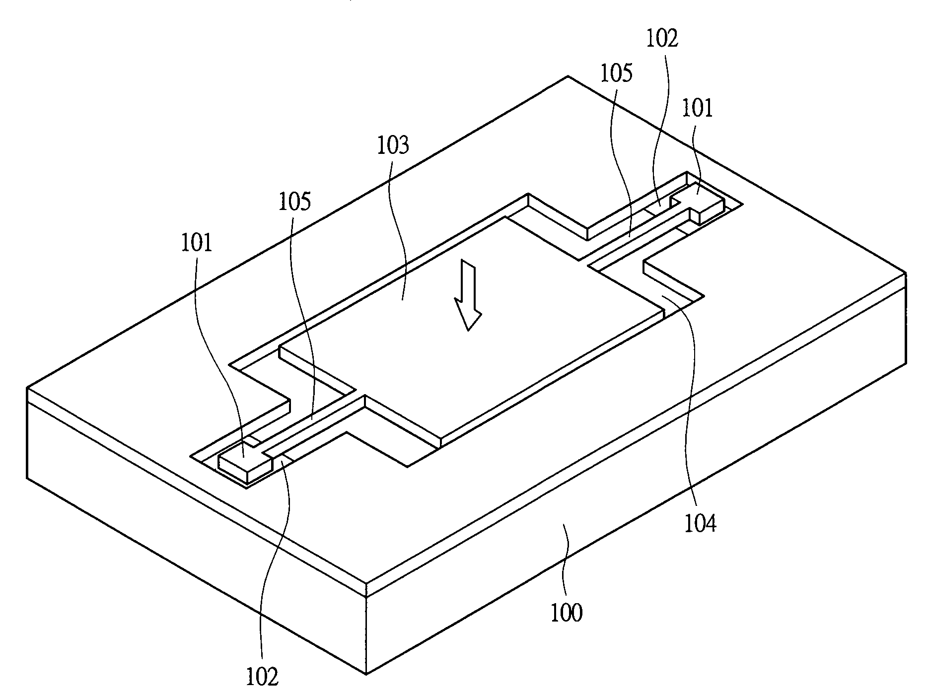
However, if the silicon wafer has a large diameter, a large angle error in alignment sometimes causes a misalignment between the bank portion 102 formed on the supporting member 100 and the fixing portion 101 formed on the silicon wafer.
In this case, deterioration in performance such as deterioration in resonance frequency of the sensor and occurrence of unwanted mode may occur.
Moreover, since variations in performance between sensors are caused, manufacturing yield is deteriorated.
Moreover, since the oxide film formed on the front surface is removed with etchant after the bonding, in a sensor having a small-sized movable toothed gear or fixing pattern such as a fixed toothed gear, the movable portion may possibly be stuck to the surrounding fixed pattern (in particular, the movable toothed gear and the fixed toothed pattern together).

Method used


Image

  • Method of manufacturing micro electro mechanical systems device
  • Method of manufacturing micro electro mechanical systems device
  • Method of manufacturing micro electro mechanical systems device

Examples


Embodiment Construction

[0031]In the embodiments described below, the invention will be described in a plurality of sections or embodiments when required as a matter of convenience. However, these sections or embodiments are not irrelevant to each other unless otherwise stated, and the one relates to the entire or a part of the other as a modification example, details, or a supplementary explanation thereof.

[0032]Also, in the embodiments described below, when referring to the number of elements (including number of pieces, values, amount, range, and the like), the number of the elements is not limited to a specific number unless otherwise stated or except the case where the number is apparently limited to a specific number in principle, and the number larger or smaller than the specified number is also applicable.

[0033]Further, in the embodiments described below, it goes without saying that the components (including element steps) are not always indispensable unless otherwise stated or except the case wher...


PUM


Abstract

Provided is a MEMS device which is robust to the misalignment and does not require the double-side wafer processing in the manufacture of a MEMS device such as an angular velocity sensor, an acceleration sensor, a combined sensor or a micromirror. After preparing a substrate having a space therein, holes are formed in a device layer at positions where fixed components such as a fixing portion, a terminal portion and a base that are fixed to a supporting substrate are to be formed, and the holes are filled with a fixing material so that the fixing material reaches the supporting substrate, thereby fixing the device layer around the holes to the supporting substrate.

Description

CROSS-REFERENCE TO RELATED APPLICATION[0001]The present application claims priority from Japanese Patent Application No. JP 2007-183159 filed on Jul. 12, 2007, the content of which is hereby incorporated by reference into this application.TECHNICAL FIELD OF THE INVENTION[0002]The present invention relates to a technology for manufacturing a Micro Electro Mechanical Systems (MEMS) device having a movable portion or a suspension portion such as an acceleration sensor, an angular velocity sensor, a resonator, a mechanical filter, or a micromirror. In particular, it relates to a technology for manufacturing a hermetically-sealed MEMS device which exchanges electric signals with the outside.BACKGROUND OF THE INVENTION[0003]For example, a MEMS device having a supporting member formed of a silicon substrate, a fixing portion formed on the supporting member, and a flat plate-shaped movable portion provided with interposing a space between the movable portion and the supporting member, in wh...

Claims


Application Information

Patent Timeline
IPC IPC(8): H01L21/50B81C1/00G01P15/08G01P15/125H01L29/84
CPCB81B2201/0235B81B2203/0307B81C1/00039B81C1/00952G01P15/125B81C2203/058G01C19/5733G01C19/5755G01P15/0802B81C2201/019
Inventor JEONG, HEEWONGOTO, YASUSHIHANAOKA, YUKOFUJIMORI, TSUKASA
Owner HITACHI LTD
Learn More