
Method and apparatus for sampling RF signals

a technology of rf signals and sampling methods, applied in the direction of transmission noise suppression, electrical equipment, transmission, etc., can solve the problems of power dissipation, too high sampling rate, complicated wireless communication apparatuses, etc., and achieve the effect of reducing the sampling ra

Inactive Publication Date: 2009-01-15
ST ERICSSON SA
View PDF6 Cites 11 Cited by
  • Summary
  • Abstract
  • Description
  • Claims
  • Application Information

AI Technical Summary

Benefits of technology

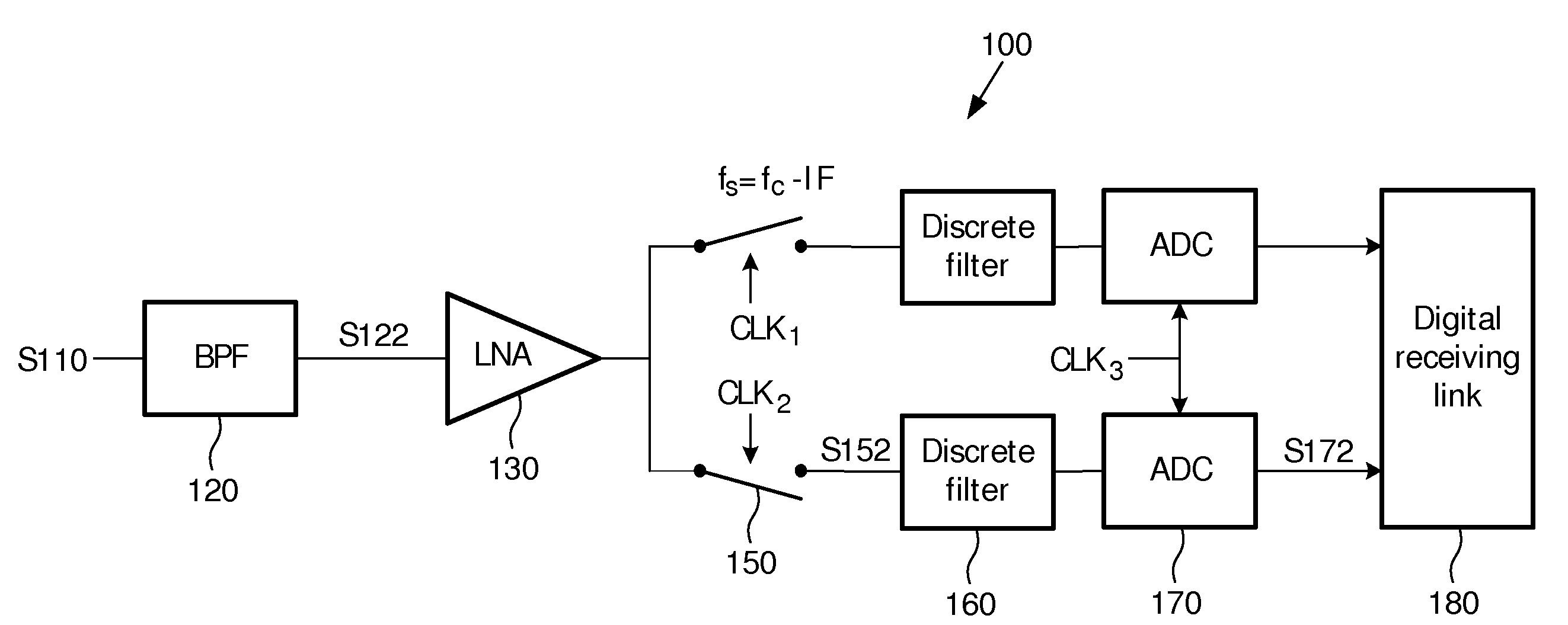
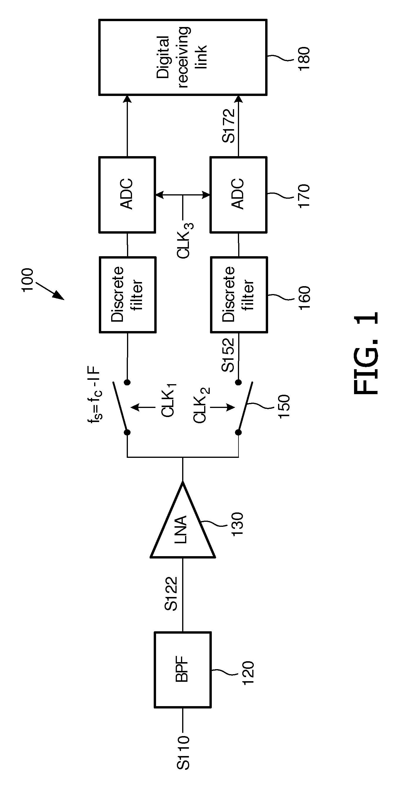
[0008]An object of the invention is to provide a method and apparatus for sampling RF signals in a receiver, particularly to provide a method and apparatus for greatly decrease the sampling rate at which the sampling is performed in RF band.
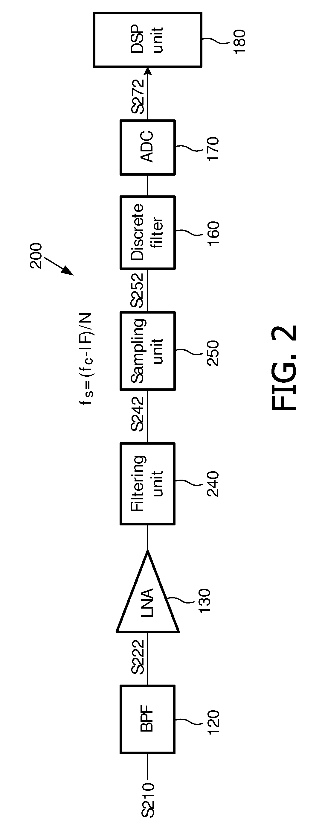
[0014]The method according the invention can avoid the aliasing of some of interference frequency components into the useful frequency component in the subsequent sampling process by filtering out interference frequency components before sampling. The center frequencies of these filtered-out interference frequency components are equal to the sum of a multiple of the sampling rate and the intermediate frequency. For other frequency components whose center frequencies are not equal to the sum of a multiple of the sampling rate and the intermediate frequency, they do not need to be filtered out because there is no aliasing into the useful frequency component due to them. Thus, the number of sampling units required for this method is limited. Moreover, the number of the required filtering units can be further decreased by combining with RF bandpass filter BPF preceding the filtering unit by which the RF signal is first bandpass filtered to suppress out-of-band interferences of the RF band at which the useful frequency component.
[0015]Since it is easy to implement a plurality of RF notch filters and the number of the required RF filter is limited, RF sampling can be simply and conveniently implemented by using the method and apparatus according the invention, and the sampling rate can be decreased to about 1 / N of the carrier frequency of the useful frequency component, which is much lower than the sampling rate in existing RF sampling scheme. The method and apparatus according the invention can greatly decrease power dissipation at the time of sampling.

Problems solved by technology

With the rapid development of wireless communication systems, wireless communication apparatuses become more and more complicated and miniaturized.
However, such a method has a drawback, i.e., the sampling rate is too high.
In general, the higher the sampling rate, the higher the power dissipation, and the more complicated the design of a sampling unit.
Therefore, it is necessary to solve the problem that the sampling rate is too high.
However, this RF bandpass filter BPF is generally bulky and costly, and it is also difficult to achieve a BPF with a narrow bandwidth.
Thus, it is difficult to use such a BPF in mobile equipment, particularly in a hand-held device.
In a practical system, it is difficult to form a BPF whose bandwidth is very narrow and accurate by connecting a plurality of wide-bandwidth BPF in series due to the limitation of performance, size, and power dissipation.

Method used


Image

  • Method and apparatus for sampling RF signals
  • Method and apparatus for sampling RF signals
  • Method and apparatus for sampling RF signals

Examples


Embodiment Construction

[0033]The technical method of the present invention will be described below in detail from the following embodiments, taken in conjunction with the accompanying drawings.

[0034]FIG. 2 is a schematic diagram showing a receiver with the RF sampling method according to one embodiment of the present invention. The receiver bandpass filters a RF signal S210 with a BPF 120 to obtain a bandpass-filtered signal S222 which is amplified by a LNA 130 and then transferred to a filtering unit 240 for filtering out at least one predefined interference frequency component from the RF signal S210; the output signal S242 from the filtering unit 240 is a notch-filtered RF signal, and, after being sampled by a sampling unit 250, it is transformed into a discrete analog signal S252; after being processed by a discrete filter 160 and an analog-to-digital converter 170, S252 is transformed into a digital signal S272; S272 is subsequently processed by a digital signal processing unit 280. The sampling rate...


PUM


Abstract

The invention provides a method and apparatus used in a receiver for sampling RF signals, particularly to provide a method and apparatus for greatly decrease the sampling rate performed in RF band. The invention provides an apparatus for sampling a RF signal including a plurality of interference frequency components and a useful frequency component, comprising: a filtering unit for filtering out at least one preset interference frequency component from the RF signal to generate a notch-filtered RF signal; a sampling unit for sampling the notch-filtered RF signal at a preset sampling rate to generate a discrete analog signal. The sampling unit can be implemented by a plurality of notch filters. RF sampling can be simply and conveniently implemented by using the method and apparatus according the invention, and the sampling rate can be decreased to about 1 / N of the carrier frequency of the useful frequency component, which is much lower than the sampling rate in existing RF sampling scheme. The method and apparatus according the invention can greatly decrease power dissipation when sampling.

Description

FIELD OF THE INVENTION[0001]The present invention relates to a wireless communication system, and more particularly, to a method and apparatus for sampling RF signals in a wireless communication system.BACKGROUND OF THE INVENTION[0002]With the rapid development of wireless communication systems, wireless communication apparatuses become more and more complicated and miniaturized. Digital signal processing techniques have inherent advantages in a complex mathematical operation, such as flexible mathematical transformation, strong computing capability, ease for implementation and the like. On the other hand, many functions can be integrated in an integrated chip by using digital signal processing techniques, so as to reduce size of apparatuses. Thus, the trend for wireless communication systems is to implement more functions by using digital signal processing techniques instead of analog signal processing techniques.[0003]RF sampling is an important research subject in various schemes...

Claims


Application Information

Patent Timeline
Patent Type & Authority Applications(United States)
IPC IPC(8): H04B1/10
CPCH04B1/30H04B1/0007
Inventor QIAN, XUECHENG
Owner ST ERICSSON SA
Learn More