Apparatus and method for decreasing an upshift delay in an automatic transmission

an automatic transmission and delay technology, applied in mechanical apparatus, digital data processing details, instruments, etc., can solve the problems of less than optimal hardware utilization for certain clutch maneuvers and less than optimal upshift delays, so as to reduce the input torque, optimize the upshift response time, and reduce the delay

Inactive Publication Date: 2009-01-15
GM GLOBAL TECH OPERATIONS LLC
View PDF53 Cites 13 Cited by
  • Summary
  • Abstract
  • Description
  • Claims
  • Application Information

AI Technical Summary

Benefits of technology

[0008]Accordingly, a method is provided for reducing an upshift delay in an automatic transmission by calculating a reduced level of input torque, engine reduction torque, or a scheduled torque value, at which an on-coming clutch may initiate a speed ratio change within a predetermined and reduced threshold time period, thereby optimizing the upshift response time.
[0009]The method includes detecting a commanded upshift, calculating the scheduled torque value as a function of an unmanaged torque value in response to the commanded upshift, and reducing an input torque value from the engine using the calculated scheduled torque value rather than the unmanaged torque value. The calculated scheduled torque value is then passed into model-based controls in order to complete the upshift event.
[0014]A method is provided for reducing a time delay between a commanded upshift and a resultant upshift event in a vehicle having an engine, an automatic transmission, a torque converter, an off-going clutch, and an on-coming clutch. The method includes detecting a commanded speed ratio change corresponding to an upshift event, calculating a scheduled torque value as a percentage reduction of an unmanaged torque level in response to the commanded speed ratio change, and calculating an on-coming torque value for the on-coming clutch and an off-going torque value for the off-going clutch during a torque phase of the upshift event using the scheduled engine reduction torque. The on-coming and off-going clutches are then applied during the torque phase using the respective calculated on-coming and off-going torque values.

Problems solved by technology

This balance in clutch-to-clutch systems may lead to less than optimal hardware utilization for certain clutch maneuvers.
A high torque upshift may require rapid pressurization or fill of the clutch chamber while overcoming compliance to rapidly initiate a desired speed ratio change, which in some circumstances may lead to less than optimal upshift delays.

Method used


Image

  • Apparatus and method for decreasing an upshift delay in an automatic transmission
  • Apparatus and method for decreasing an upshift delay in an automatic transmission
  • Apparatus and method for decreasing an upshift delay in an automatic transmission

Examples


Embodiment Construction

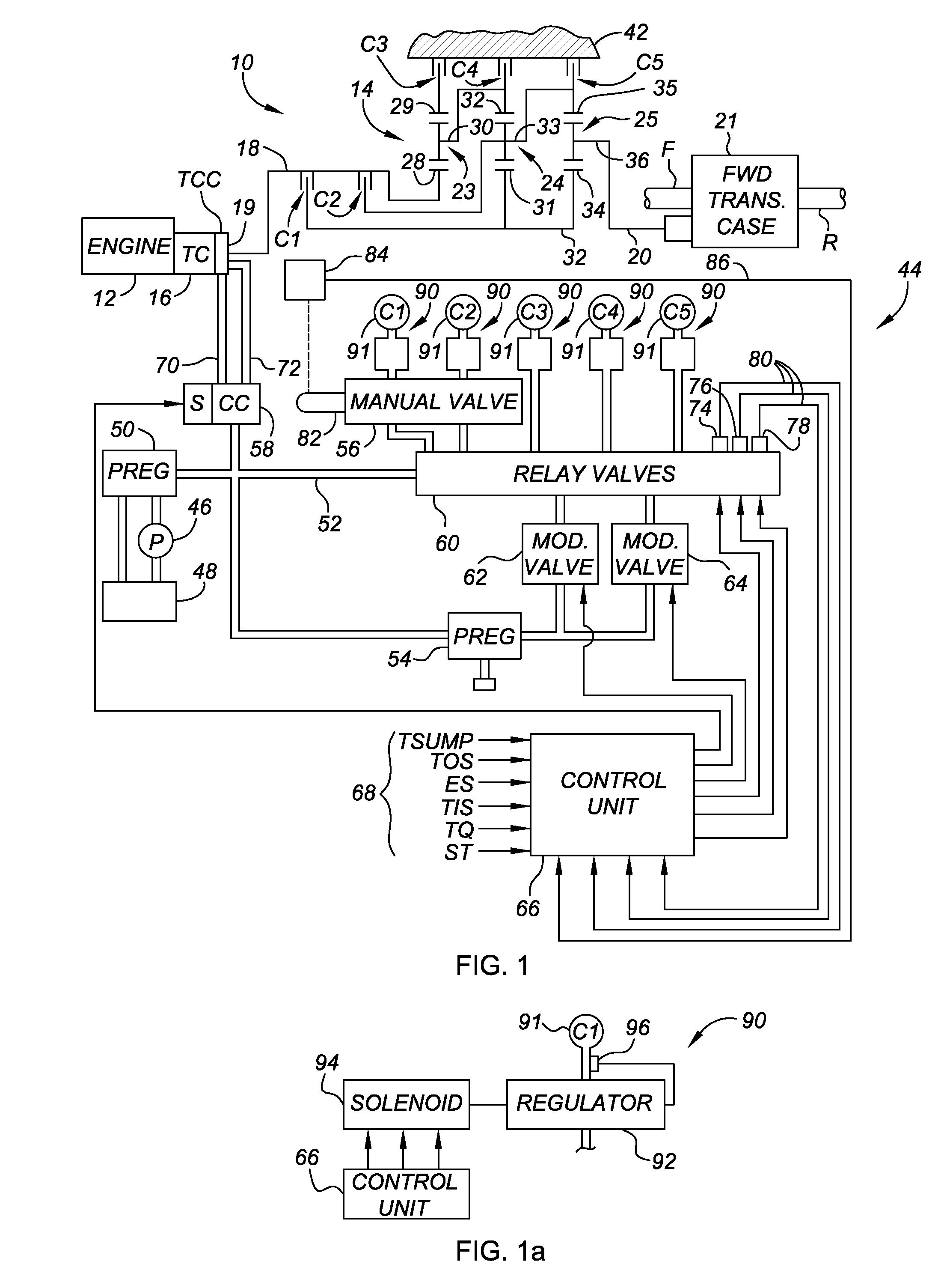
[0023]Referring to FIG. 1, the reference numeral 10 generally designates a preferred vehicle power train including an engine 12, a transmission 14, and a torque converter 16 (TC) providing a fluid coupling between engine 12 and a transmission input shaft 18. While the invention will be described as being used with a conventional engine 12, alternate power sources such as an electric motor or hybrid electric / gas motor may be implemented as well within the scope of the invention. Engine output may be controlled as necessary to change an actual value of an input torque to transmission 14 as needed to calculate an optimal value of transmission input torque, as explained below with reference to FIG. 3. A reduction of engine torque may be accomplished, for example, by controlled spark arrest, and an increase of engine torque is accomplished by opening the throttle. It should be appreciated, however, that there are numerous methods for increasing and / or decreasing engine torque, as will be...


PUM


Abstract

A method reduces a time delay or lag between a commanded upshift and a resultant upshift event in vehicle. The method detects the commanded upshift, calculates a scheduled engine torque reduction torque value as a function of an unmanaged torque, and reduces an input torque value from the engine using the calculated scheduled torque. A powertain includes an engine, a transmission, a torque converter, clutches that are selectively engageable to provide at least six forward speed ratios, a reverse speed ratio, and a neutral condition, and a controller. The controller has an algorithm controlling an operation of an off-going clutch and the on-coming clutch during a speed ratio change representing an upshift event. The algorithm calculates a scheduled torque value as a percentage of an unmanaged torque level of the engine, and controls the off-going and on-coming clutch through the speed ratio change using the calculated scheduled torque value.

Description

CLAIM OF PRIORITY[0001]This application claims priority to U.S. Provisional Patent Application No. 60 / 949,037, filed on Jul. 11, 2007, which is hereby incorporated by reference in its entirety.TECHNICAL FIELD[0002]The present invention relates to a method and apparatus for optimizing the responsiveness of a shift event in an automatic transmission by decreasing a delay in the initiation of a commanded upshift according to a calculated or ramped requested clutch torque.BACKGROUND OF THE INVENTION[0003]An automatic transmission for a motor vehicle generally includes a number of gear elements coupling an input and output shaft, and a number of torque-transmitting devices that are selectively engageable to thereby activate certain gear elements, thus establishing a desired speed ratio between the input and output shafts. As used herein, the term “torque-transmitting device” will be used collectively to refer to brakes as well as rotating clutches.[0004]The transmission input shaft is ty...

Claims


Application Information

Patent Timeline
Patent Type & Authority Applications(United States)
IPC IPC(8): B60W10/10B60W10/02B60W10/04
CPCF16H61/0204Y10T477/677F16H2302/00F16H61/686
Inventor WHITTON, MATTHEW D.
Owner GM GLOBAL TECH OPERATIONS LLC
Why Eureka
Try Eureka