Diesel particulate filter regeneration system

a technology of dpf filter and regeneration system, which is applied in the direction of mechanical equipment, machines/engines, electric control, etc., can solve the problems of reducing the overall fuel efficiency of the internal combustion engine system, increasing the emissions during the regeneration process, and dpf regeneration energy loss can become particularly significant, so as to improve the efficiency of dpf filter regeneration

Inactive Publication Date: 2009-01-22
UNITED STATES OF AMERICA AS REPRESENTED BY U S ENVIRONMENTAL PROTECTION AGENCY THE
View PDF11 Cites 12 Cited by
  • Summary
  • Abstract
  • Description
  • Claims
  • Application Information

AI Technical Summary

Benefits of technology

[0010]In a second embodiment of the invention, a flow redirection device is placed within each DPF filter, to dire

Problems solved by technology

Nevertheless, by requiring electrical energy and/or the use of additional fuel, each of these active regeneration methods reduce the overall fuel efficiency of the internal combustion engine system.
The energy lost in DPF regeneration can become particularly significant in engine systems with relatively cool exhaust temperatures and/or with particularly high engine-out PM levels, such as low temperature diesel combustion systems that use high levels of exhaust gas recirculation for reduced emissions of NOx.
While some have already advocated one way of improving the efficiency of DPF regene

Method used


Image

  • Diesel particulate filter regeneration system
  • Diesel particulate filter regeneration system
  • Diesel particulate filter regeneration system

Examples


Embodiment Construction

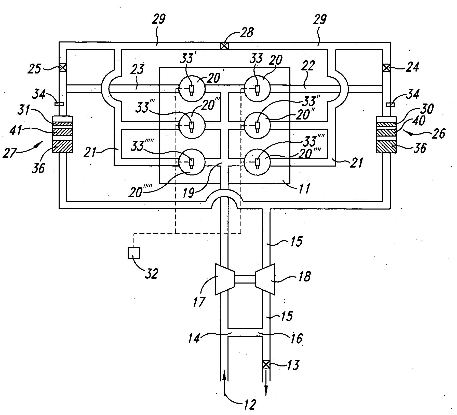
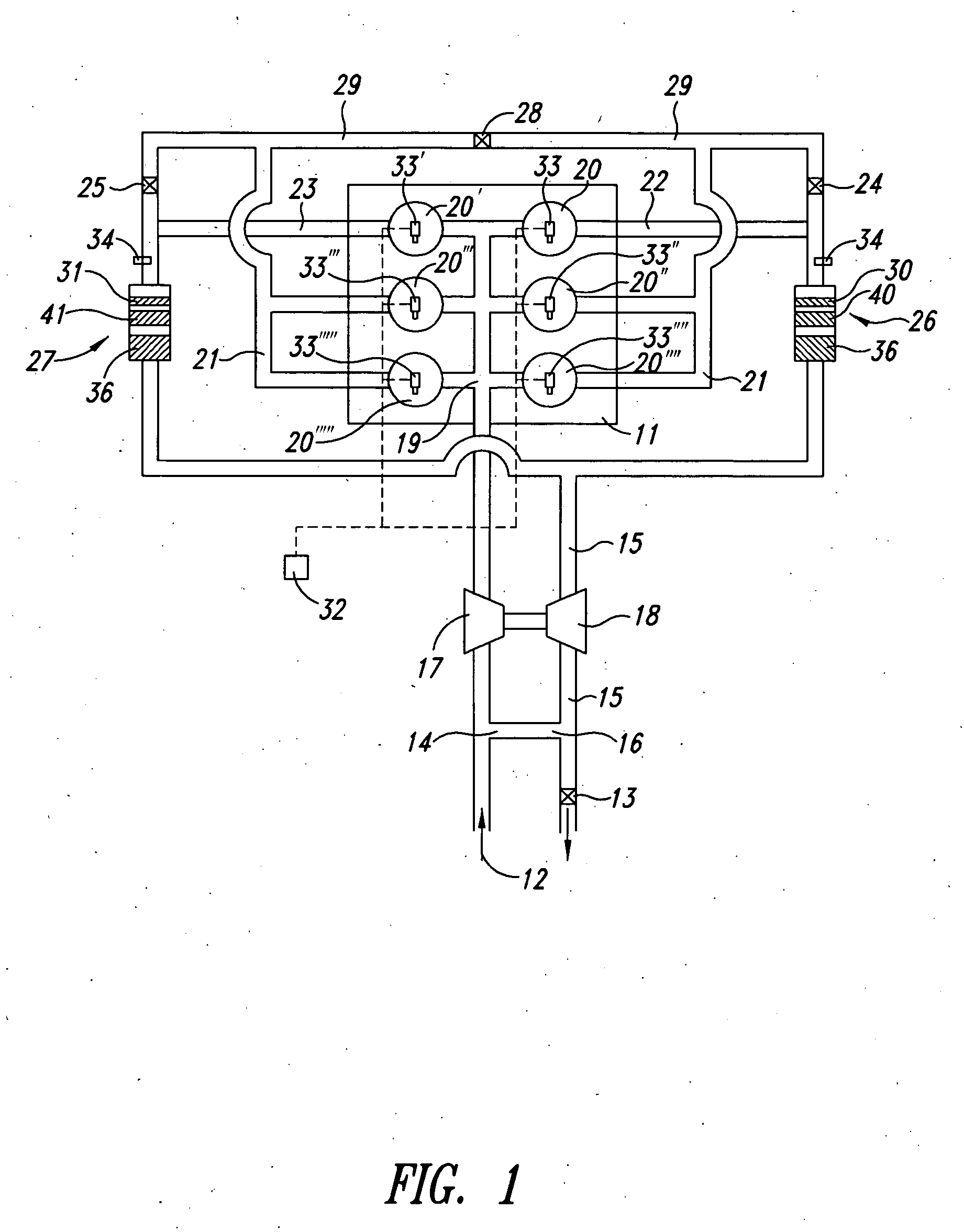
[0015]FIG. 1 portrays a preferred embodiment for the present invention. Intake air enters the intake system at port 12. Exhaust gas is mixed with the intake air (forming a charge-air mixture) at port 14, with EGR control valve 13 in the exhaust line 15 adjustably creating an exhaust backpressure to force exhaust gas to flow through port 16 to port 14 in a desired amount. The charge-air then flows through low pressure compressor 17, which may be driven, by turbine / motor 18. Alternatively, a multi-stage turbocharging system or other boost system may be used, as will be known in the art.

[0016]Continuing with FIG. 1, the charge-air eventually enters engine 11 through intake manifold 19. Engine 11 comprises a plurality of combustion cylinders 20, 20′, 20″, 20′″, etc formed in the engine block, as known in the art. The total number of cylinders utilized may be any number desired for the application. The charge-air enters a combustion chamber (not shown) of each respective cylinder 20, 20′...


PUM


Abstract

A diesel combustion engine comprises multiple particulate filters and corresponding exhaust piping and valving in the exhaust manifold and/or exhaust line, configured to enable regeneration to occur in one of the DPF filters through heating the exhaust from a single cylinder of the engine, while the exhaust from the remaining cylinders is temporarily routed through the other DPF filter during the regeneration event. Flow redirection devices are placed within the DPF filters to direct flow of exhaust gas through the DPF filters during regeneration in a manner to facilitate complete regeneration, including in outer volumes along the interior walls of the DPF filters.

Description

[0001]This application claims priority from U.S. provisional application 60 / 933,288, “Diesel Particulate Filter Regeneration System,” filed Jun. 5, 2007.FIELD OF THE INVENTION[0002]This invention relates to devices and methods for active regeneration of diesel particulate filters, for efficient emissions reduction for diesel engine exhaust.BACKGROUND AND DESCRIPTION OF THE PRIOR ART[0003]Diesel particulate filters (aka DPFs or PM filters) are gaining acceptance for reducing emissions of harmful particulate matter (PM) from diesel internal combustion engines. DPFs are an aftertreatment technology, generally being placed in the exhaust line downstream of the engine to catch particulate matter within the filter to prevent the harmful material from being released into the atmosphere.[0004]In some circumstances, active regeneration of the DPF is needed to clear the DPF of accumulated particulate matter so that the DPF can continue to operate effectively in removing additional PM from the...

Claims


Application Information

Patent Timeline
IPC IPC(8): F01N3/023F01N3/032
CPCF01N3/027F01N3/032F01N3/035F01N9/002F01N13/107F01N2240/20F01N13/011F01N2340/06F02B37/00F02D41/008F02D41/0245F02D41/029Y02T10/47F01N2290/00Y02T10/40
Inventor GRAY, JR., CHARLES L.
Owner UNITED STATES OF AMERICA AS REPRESENTED BY U S ENVIRONMENTAL PROTECTION AGENCY THE
Why Eureka
Try Eureka