
A/v cooling system and method

Inactive Publication Date: 2009-01-22
AMERICA POWER CONVERSION CORP
View PDF99 Cites 25 Cited by
  • Summary
  • Abstract
  • Description
  • Claims
  • Application Information

AI Technical Summary

Benefits of technology

[0013]Some embodiments further comprise at least one control system configured to operate the audio-visual cooling system. In some embodiments, the control system is configured to receive at least one first indication that the at least one unit of audio-visual equipment is in operation and to operate a heat exchanger to supply the refrigerant. In some embodiments, the at least one indication includes at least one of an indication of a temperature of air within the housing unit and an indication of a power consumption within the housing unit. In some embodiments, the control system is configured to receive at least one second indication that the at least one unit of audio-visual equipment is no longer in operation and to operate the heat exchanger to stop supplying the refrigerant. In some embodiments, the control system is further configured to determine if the audio-visual cooling system is configured to provide sufficient cooling for the at least one unit of audio-visual equipment operating within t

Problems solved by technology

Similar to most electronic equipment, consumer and professional audio-visual (A / V) equipment (e.g., stereo receivers, media players / recorders, public address (PA) systems, DVD, CD, DAT (digital audio tape), special effects encode / decode, analog to digital and digital to analog conversion, flash and hard disk memory devices, editing / mastering equipment may be adversely affected by heat, such as heat generated by the operation of the A / V equipment.
Such combined operation increases potential heat related problems associated with A / V equipment.
However, such methods rely substantially on conduction of heat through the walls of the room in which the rack is installed to ultimately remove heat.
Since building walls are often designed to have deliberately high thermal resistance for the purpose of minimizing air conditioning and heating load, the ability of a wall to conduct heat away from the A / V equipment being cooled may be limited.
Therefore, while this method may be successfully employed for some low power A / V equipment (e.g., up to hundreds of watts) in lower density configurations, it may be unsuccessful in accommodating large heat loads (e.g., thousands of watts) and / or high density configurations.
When this method of cooling is attempted with such high power and / or high density A / V equipment, the result may be a steadily escalating ambient temperature in the room where the A / V equipment is located until such point as heat loss through the walls of the room is equal to the rate of heat introduction from A / V equipment.
This temperature may be so high as to cause temporary malfunction or permanent damage to the A / V equipment.
Such building cooling systems generally are not designed to accommodate heat loads beyond that generated from personnel occupancy, environmental, and lighting.
Therefore, the placement of additional heat load from A / V equipment operating in the building may result in overloading, tripping offline as a protective action, and / or causing permanent damage and failure of the building cooling system.
Further, building cooling systems are often not designed to be operable year-round, yet there is nearly always an expectation that A / V equipment be available for use during all seasons of the year.
Furthermore, due to the extremely high audio dynamic range with which high-end A / V equipment is capable of operating, any noise from sources other the A / V media itself may be regarded as objectionable and often unacceptable by users of the equipment, so noise associated with forced movement of air, and therefore such building cooling systems may be judged to be an excessive and undesired source of noise, thereby prohibiting use for cooling in the room in which the A / V equipment is located.
Such fans and / or compressor(s) at the point of cooling generate noise near the A / V equipment.
Due to the close proximity of such systems to the A / V equipment, the sound generated by the cooling system may often be judged to be unacceptable by users of A / V equipment.
This method, however, suffers from noise caused by air movement which may be unacceptable to users of the A / V equipment.
The problem with this method is that the source of replacement air is often unconditioned, and therefore operation of the exhaust fan may result in significantly increased load on the building cooling system.

Method used


Image

  • A/v cooling system and method
  • A/v cooling system and method
  • A/v cooling system and method

Examples


Embodiment Construction

[0028]Embodiments are not limited in their application to the details of construction and the arrangement of components set forth in the following description or illustrated in the drawings. Embodiments are capable of being practiced or of being carried out in various ways. Also, the phraseology and terminology used herein is for the purpose of description and should not be regarded as limiting. The use of “including,”“comprising,”“having,”“containing,”“involving,” and variations thereof herein, is meant to encompass the items listed thereafter and equivalents thereof as well as additional items.

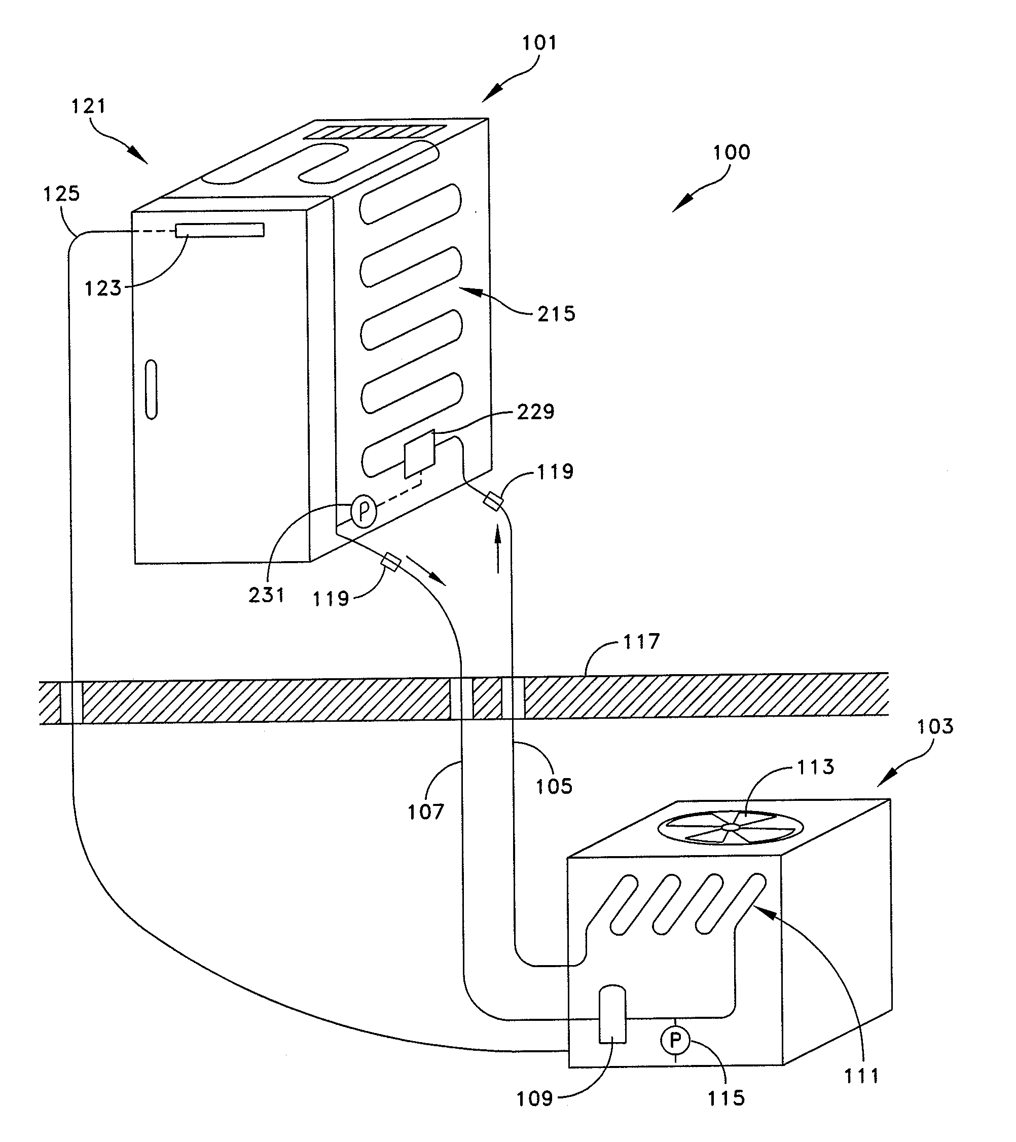
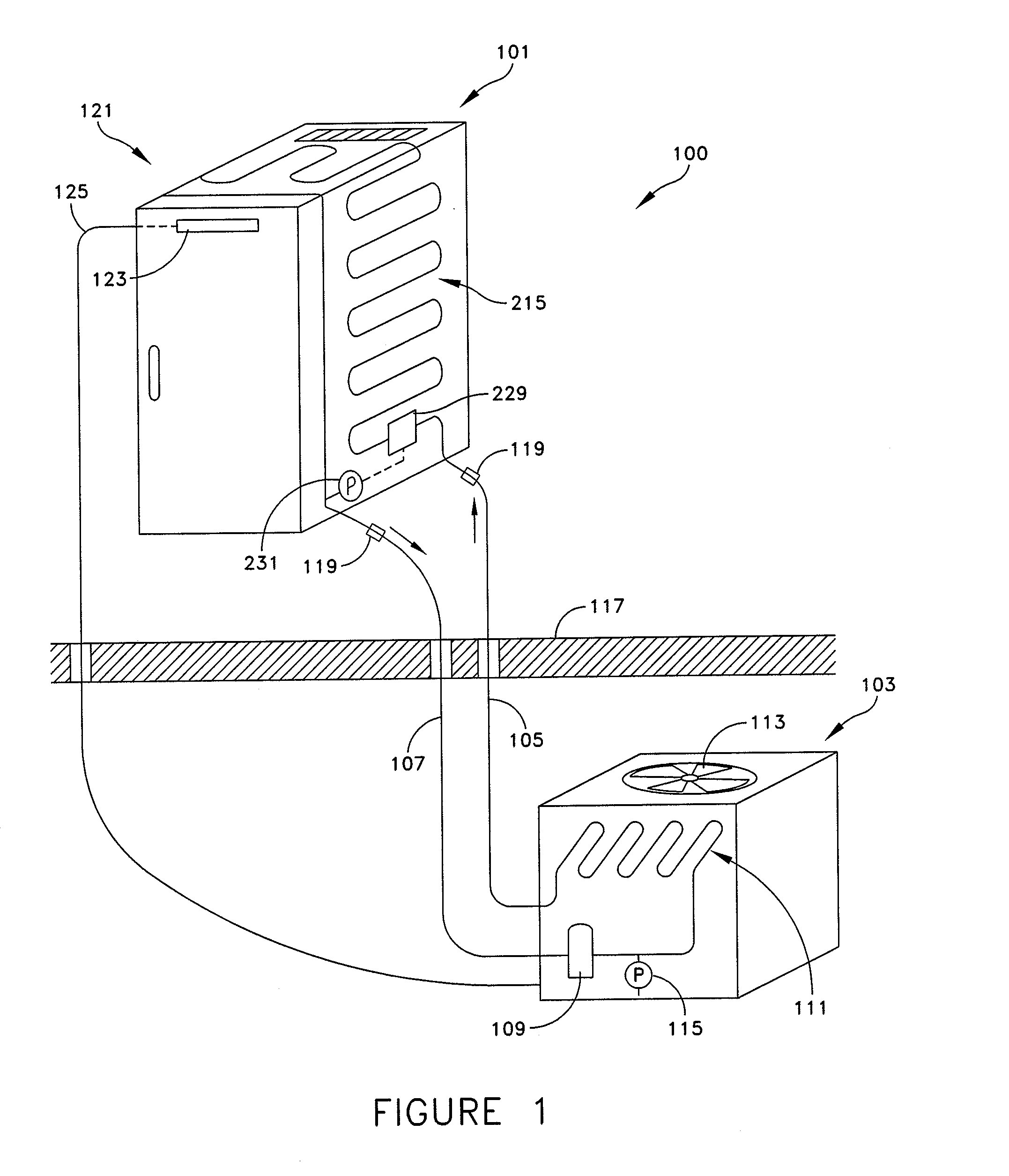
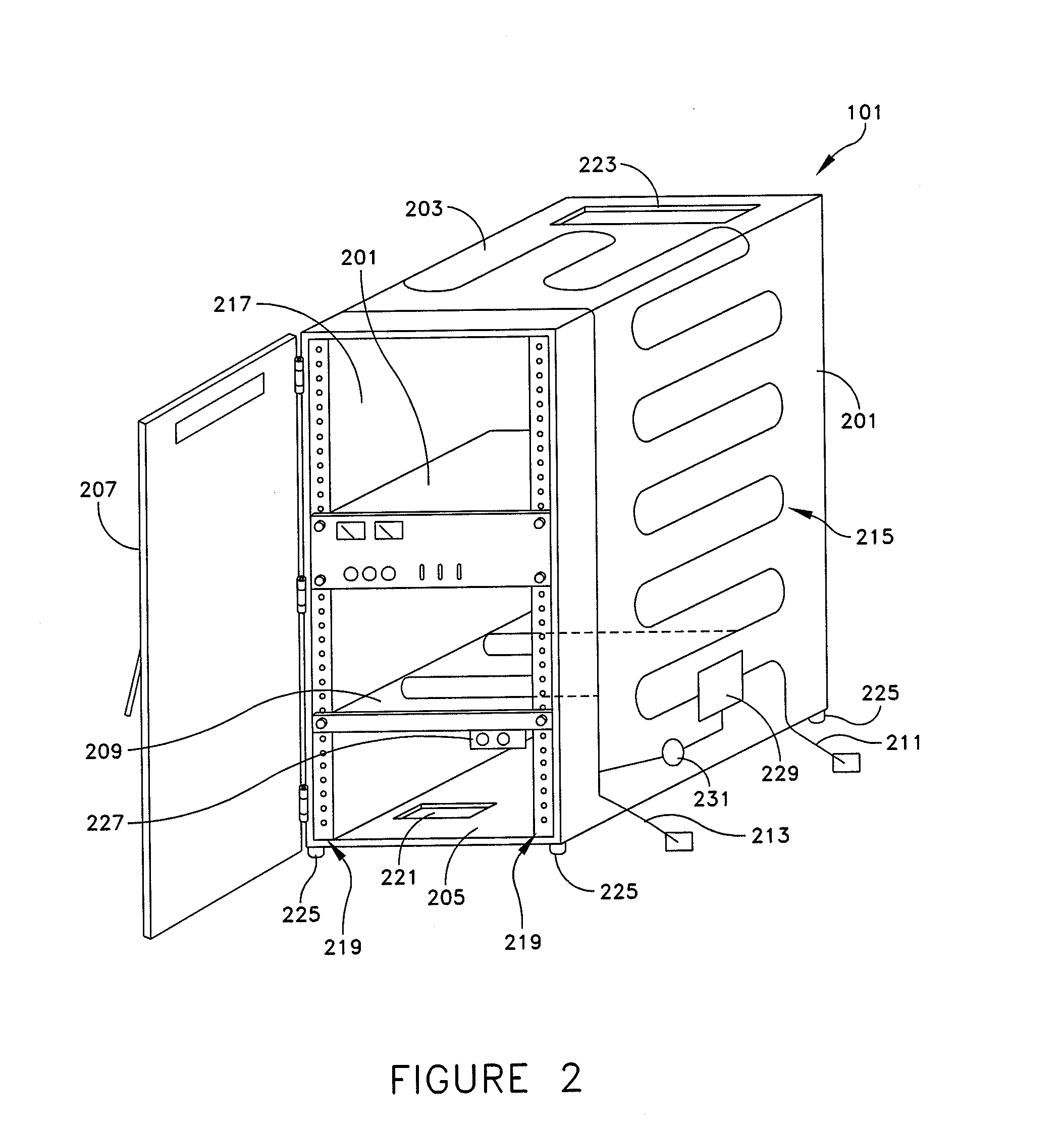
[0029]In one aspect, it is recognized that an A / V cooling system may be arranged to provide quiet and effective cooling for consumer and professional A / V equipment. In some embodiments, the A / V cooling system may use natural convection within an A / V housing unit supplemented with a refrigerant flow through structural elements of the A / V housing unit to cool the A / V equipment. Natural convect...


PUM


Abstract

An audio-visual support and cooling system to maintain A / V equipment at a desired condition. The system comprises a housing unit configured to support at least one unit of A / V equipment. The housing includes a refrigerant inlet, a refrigerant outlet, and a plurality of structural elements configured to define a configuration of the housing, wherein at least one structural element of the plurality of structural elements includes a refrigerant path configured to direct a refrigerant through the at least one structural element between the refrigerant inlet and the refrigerant outlet. Other embodiments and methods are disclosed.

Description

BACKGROUND OF INVENTION[0001]1. Field of Invention[0002]Embodiments relate generally to apparatuses and methods for cooling electronic equipment. Specifically, embodiments relate to cooling audio-visual equipment without generating unacceptable noise.[0003]2. Discussion of Related Art[0004]Similar to most electronic equipment, consumer and professional audio-visual (A / V) equipment (e.g., stereo receivers, media players / recorders, public address (PA) systems, DVD, CD, DAT (digital audio tape), special effects encode / decode, analog to digital and digital to analog conversion, flash and hard disk memory devices, editing / mastering equipment may be adversely affected by heat, such as heat generated by the operation of the A / V equipment. Such adverse effects are of particular concern for high density and high power usage equipment that is becoming more typical of high-end consumer and professional A / V equipment. A typical storage configuration for multiple pieces of A / V equipment includes...

Claims


Application Information

Patent Timeline
IPC IPC(8): F25D17/00F25B49/00F25B49/02G01K13/00F25D23/12
CPCH05K7/20763G11B33/08G11B33/14
Inventor FINK, JAMES R.VANGILDER, JAMES W.BEAN, JR., JOHN H.
Owner AMERICA POWER CONVERSION CORP
Learn More