Integrated Vehicle Cooling System

a vehicle cooling and integrated technology, applied in the direction of machines/engines, mechanical equipment, transportation and packaging, etc., can solve the problems of inability to resize the engine cooling system, electrical components generate heat which must be dissipated, etc., to reduce the burden of vehicle cost and packaging, and the effect of cooling performan

Active Publication Date: 2009-01-22
GM GLOBAL TECH OPERATIONS LLC
View PDF24 Cites 28 Cited by
  • Summary
  • Abstract
  • Description
  • Claims
  • Application Information

AI Technical Summary

Benefits of technology

[0011]The present invention is an integrated high and moderate temperature cooling system both for the internal combustion engine (including the transmission) and for the auxiliary components of the motor vehicle, wherein the integrat

Problems solved by technology

Problematically, these electrical components generate heat which must be dissipated in order to operate within predetermined parameters.
Due to the amount of heat that is reject

Method used


Image

  • Integrated Vehicle Cooling System
  • Integrated Vehicle Cooling System
  • Integrated Vehicle Cooling System

Examples


Embodiment Construction

[0027]Referring now to the Drawing, FIGS. 2A through 6 depict various structural and functional aspects of an integrated cooling system for a motor vehicle according to the present invention.

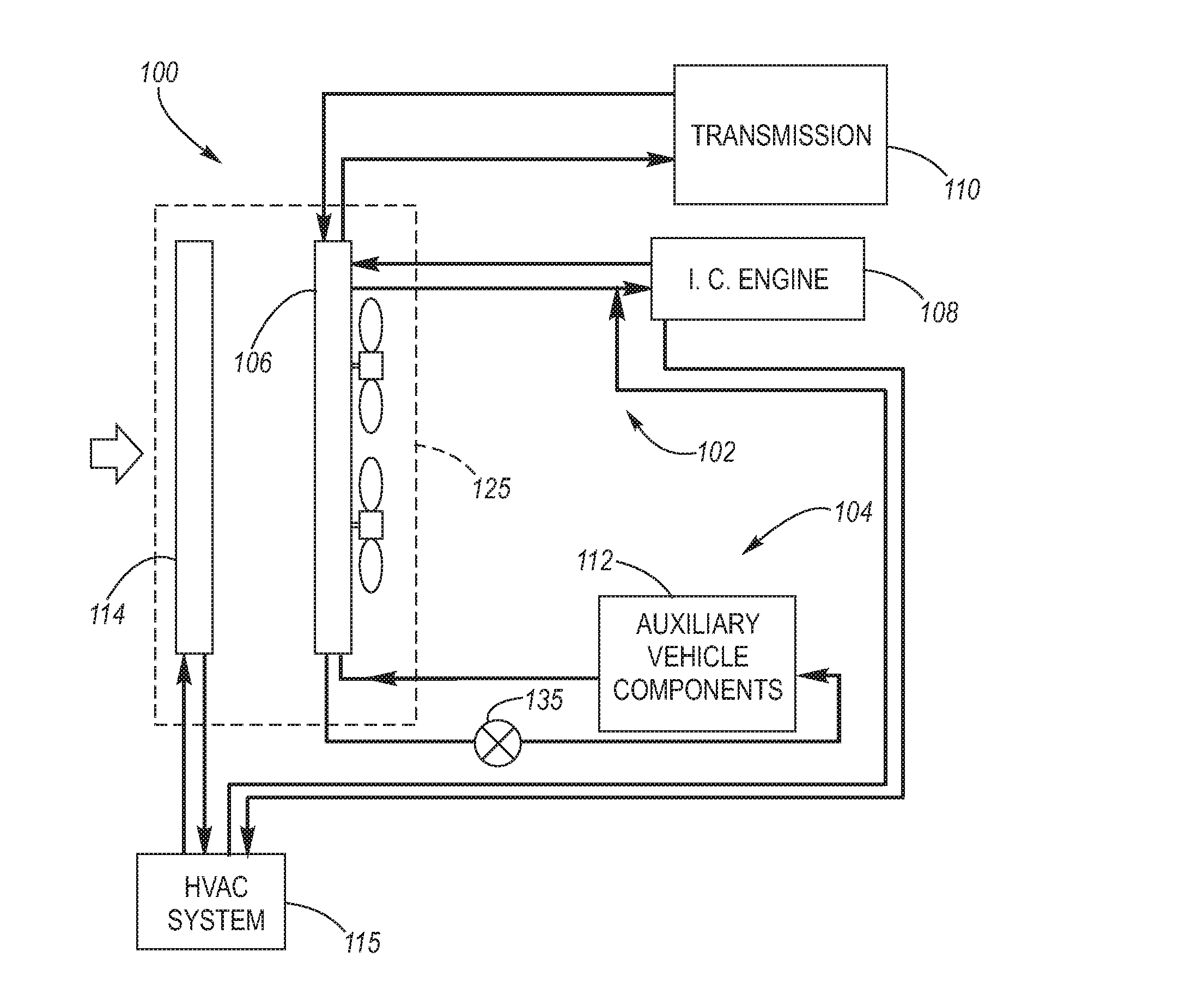
[0028]Turning attention firstly to FIGS. 2A and 2B, an overview of the general aspects of an integrated cooling system 100 according to the present invention is depicted.

[0029]As shown at FIG. 2A, the integrated cooling system 100 provides shared coolant via piping with respect to a shared heat exchanger 106. The shared coolant is stratified so as to retain thermal identity as between an engine coolant portion and an auxiliary coolant portion thereof (i.e., each retains its own thermal identity). The engine coolant portion of the shared coolant is utilized in a hot temperature cooling subsystem 102 of the integrated cooling system 100 which is needed for, and used at, the engine 108 and, if desired also the transmission 110. The auxiliary coolant portion of the shared coolant is utilized in a mo...


PUM


Abstract

An integrated high and moderate temperature cooling system both for an internal combustion engine and for auxiliary vehicle components requiring cooling. The integrated cooling system shares a coolant, yet the shared coolant is stratified to retain thermal identity between the portion of the coolant used for engine cooling and the portion of the coolant used for auxiliary vehicle components cooling. A shared coolant reservoir is used; preferably a shared heat exchanger, and optionally a common coolant pump may also be used.

Description

TECHNICAL FIELD[0001]The present invention relates to high temperature (i.e., fast flow rate) cooling systems of the type used to cool internal combustion engines and further relates to moderate temperature (i.e., low flow rate) cooling systems of the type used to cool vehicle electronics, as for example those associated with hybrid and fuel cell motor vehicles. Still more particularly, the present invention relates to an integrated vehicle cooling system in which components of the high and moderate temperature cooling systems are shared.BACKGROUND OF THE INVENTION[0002]As for example shown at FIG. 1A, a prior art motor vehicle has a high temperature, fast flow rate, cooling system 10 for cooling the internal combustion engine 20 via engine coolant heat exchange with the atmosphere at an engine heat exchanger (radiator) 12, and further has a moderate (low to middle-range) temperature, low flow rate, cooling system 14 for cooling of auxiliary vehicle components 22, as for example veh...

Claims


Application Information

Patent Timeline
IPC IPC(8): F01P3/12
CPCB60K11/02F01P2050/24F01P11/029F01P7/165
Inventor CLAYPOLE, GEORGE M.NEMESH, MARK D.
Owner GM GLOBAL TECH OPERATIONS LLC
Why Eureka
Try Eureka