
Degassing method and apparatus for separating gas from liquids and possibly solids

a gas separation and liquid technology, applied in the direction of separation process, liquid degasification, filtration separation, etc., can solve the problems of manual cleaning and possible clogging, and achieve the effect of convenient cleaning or purging

Active Publication Date: 2009-01-22
ANDRITZ INC
View PDF9 Cites 5 Cited by
  • Summary
  • Abstract
  • Description
  • Claims
  • Application Information

AI Technical Summary

Benefits of technology

[0010]In another aspect, certain embodiments of the present invention generally relate to an inlet design that facilitates separation of any solids (e.g., pulp, etc.) by reducing the velocity of the inlet stream on entry into the degasser. For example, this may be done using a flange. Facilitating the separation of solids may prevent clogging.

Problems solved by technology

As solids (e.g., pulp, etc.) accumulate at the base of the degasser, there is a potential for clogging.
That is, the periodic, manual cleaning may work well because a low-solids content will generally require a relatively long period of time before cleaning becomes necessary.

Method used


Image

  • Degassing method and apparatus for separating gas from liquids and possibly solids
  • Degassing method and apparatus for separating gas from liquids and possibly solids
  • Degassing method and apparatus for separating gas from liquids and possibly solids

Examples


Embodiment Construction

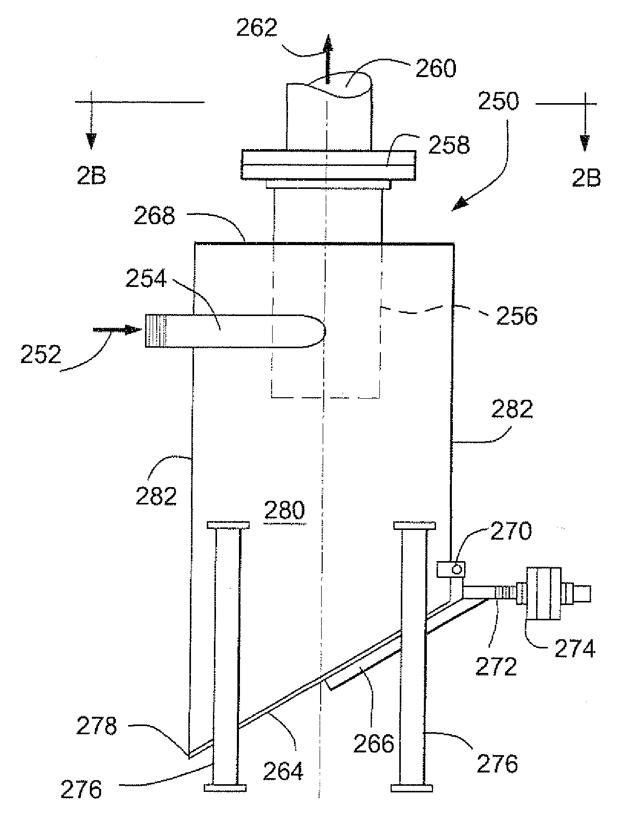
[0015]The present invention generally relates to a system for separating gasses (such as carbon dioxide, carbon monoxide, oxygen, methane, etc.) from a process stream including liquids and possibly solids. The liquid may comprise primarily water. In a preferred embodiment, the present invention has particular utility in a process for oxygen delignification in pulping and paper making. For example, the present invention may be used in conjunction with a stock pump between pressurized stages, e.g., in a system utilizing low pressure steam.

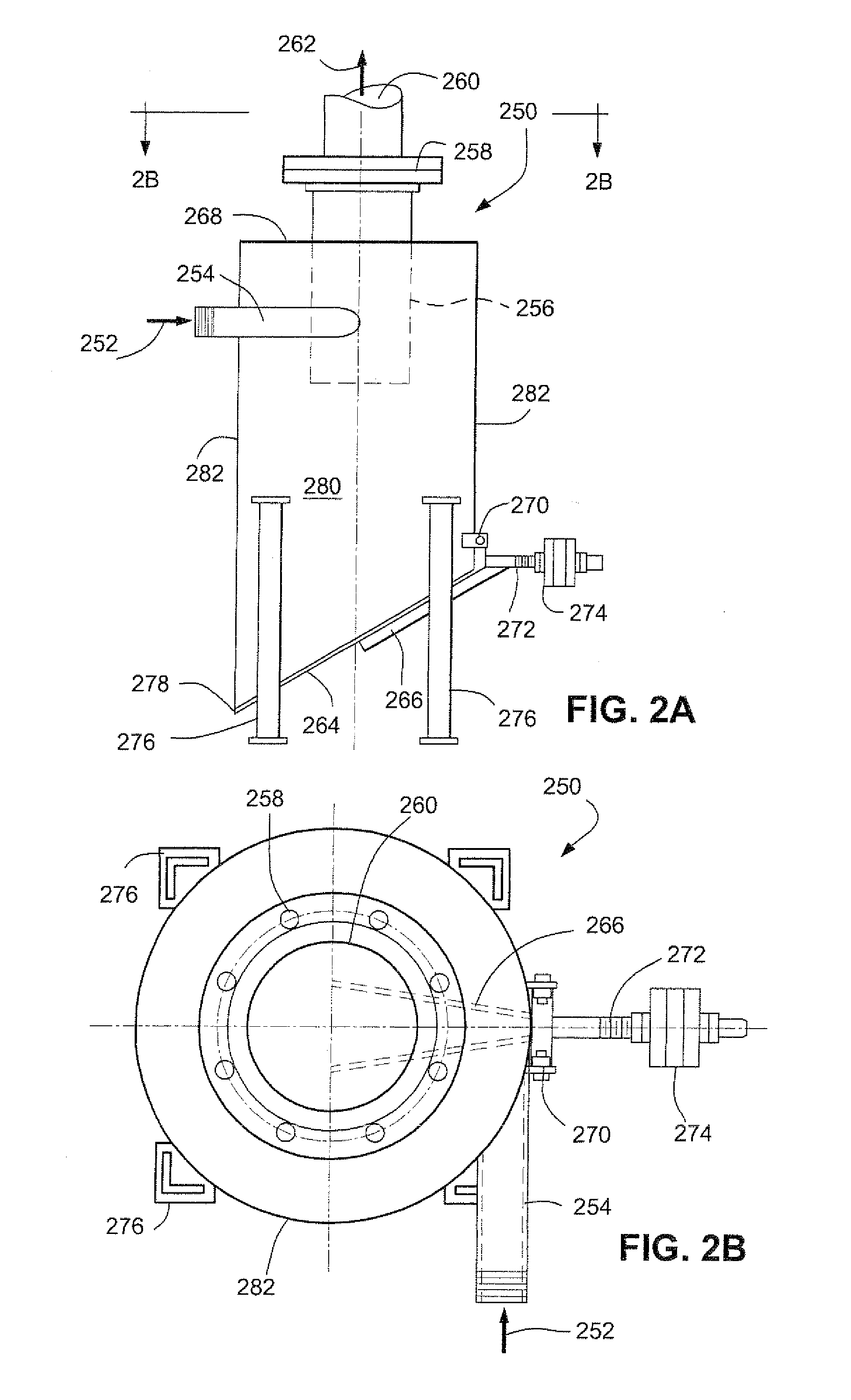
[0016]FIGS. 2A and 2B illustrate a preferred embodiment of the present invention, namely degasser 250. FIG. 2B shows a cross-sectional view (2B-2B) of the process shown in FIG. 2A, and like items are identified with like numerals. The liquid-gas stream 252 (which may contain solids, such as pulp, stock, etc.) enters via inlet pipe 254.

[0017]As compared to some prior art processes (such as the one described in FIGS. 1A and 1B), the inlet pipe enters a...


PUM

PropertyMeasurementUnit
angleaaaaaaaaaa
angleaaaaaaaaaa
angleaaaaaaaaaa

Abstract

A degasser having a flapper opening including a hinge. The hinge may permit purging of any liquids and solids without regular human intervention. There may be a fixed opening at the base of the degasser, such that there is a constant emptying from the bottom of the tank. The separation of gas from liquid may be involved in applications pertaining to pulping and oxygen delignification.

Description

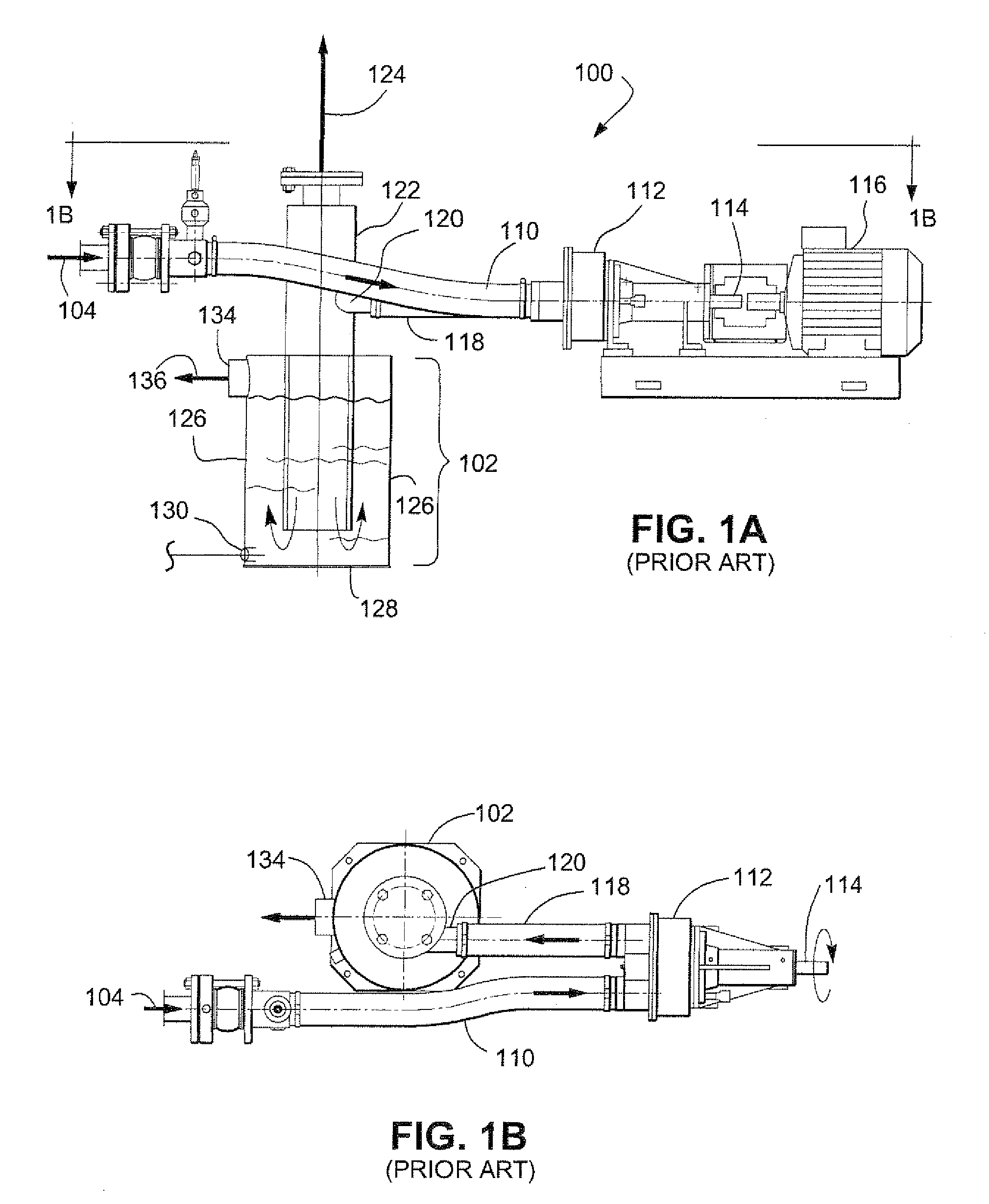
RELATED APPLICATION[0001]This application claims the benefit of U.S. Patent Application Ser. No. 60 / 950,239, filed Jul. 17, 2007, which is incorporated by reference in its entirety.BACKGROUND AND SUMMARY OF THE INVENTION[0002]The present invention generally relates to the separation of gas from liquid, particularly with respect to applications pertaining to pulping and oxygen delignification.[0003]Degassing unit operations are known. For example, a conventional degasser is illustrated in FIGS. 1A and 1B. FIG. 1B shows a cross-sectional view (1B-1B) of the process shown in FIG. 1A, and like items are identified with like numerals. The system 100 includes input stream 104, and output streams 124 and 136. Input stream 104 may include liquids and gasses. The liquids may comprise primarily water, and the gasses may include process waste gasses, such as carbon dioxide, carbon monoxide, oxygen, methane, etc. The system 100 separates these gases, which may exit primarily via output stream 1...

Claims


Application Information

Patent Timeline
Patent Type & Authority Applications(United States)
IPC IPC(8): B01D21/24B01D21/30
CPCB01D19/0036
Inventor HUNT, TYSON BRADFORDFLOYD, JERRY M.
Owner ANDRITZ INC
Learn More