
Control circuit for thermostatic oven in oven controlled crystal oscillator

a control circuit and thermostatic oven technology, applied in piezoelectric/electrostrictive/magnetostrictive devices, ohmic-resistance heating, oscillator generators, etc., can solve problems such as insufficient, and achieve the effect of more stable oscillation frequency

Inactive Publication Date: 2009-01-22
NIHON DEMPA KOGYO CO LTD
View PDF4 Cites 8 Cited by
  • Summary
  • Abstract
  • Description
  • Claims
  • Application Information

AI Technical Summary

Benefits of technology

[0015]The present invention has been made in view of the foregoing situations, and it is an object of the invention to provide a control circuit for a thermostatic oven in an oven controlled crystal oscillator, which is capable of further improving stability of the oscillation frequency thereof.
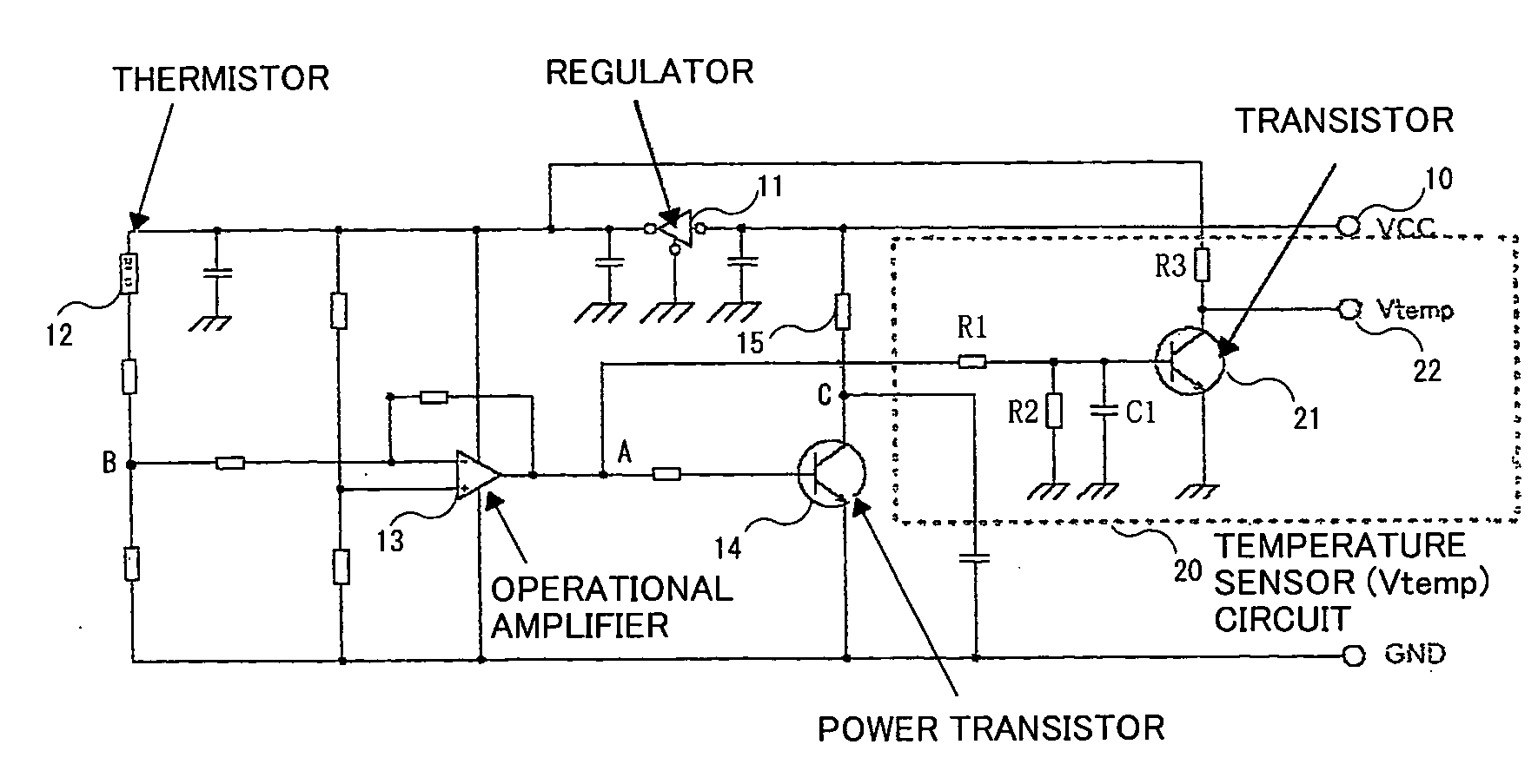
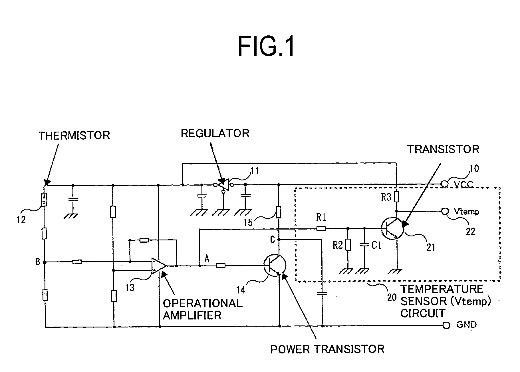
[0017]To overcome the problems of the related arts, according to one aspect of the invention, there is provided a control circuit which is provided in contact with a thermostatic oven in an oven controlled crystal oscillator to control the thermostatic oven, and includes a heater having one end supplied with a supply voltage to generate heat, a regulator that stabilizes the supply voltage, a thermistor having one end supplied with the supply voltage via the regulator, and an other end from which a voltage according to a temperature is output with a resistance value being variable according to the temperature, an operational amplifier having one input terminal to which a divided voltage of the voltage according to the temperature at the other end of the thermistor is input, an other input terminal to which a reference voltage is input, and an output fed back to the one input terminal to amplify a difference between the reference voltage at the other input terminal and the voltage at the one input terminal, a power transistor that has a collector connected with an other end of the heater, a base to which the output of the operational amplifier is input, and an emitter grounded, and controls the generated heat of the heater, and an internal temperature detection circuit that amplifies a voltage according to an ambient temperature of the thermostatic oven inside the crystal oscillator, and outputs the amplified voltage. It is possible to output a signal indicative of the temperature inside the crystal oscillator having a crystal resonator disposed therein, and perform temperature compensation based on the signal, thereby making the oscillation frequency of the oven controlled crystal oscillator more stable.
[0022]According to another aspect of the present invention, there is provided an oven controlled crystal oscillator provided with means that controls a frequency of an oscillator according to a voltage from the output terminal of the temperature sensor circuit in the above-described control circuit, thus making it possible to output a signal indicative of the temperature inside the crystal oscillator having a crystal resonator disposed therein, and perform temperature-based compensation for the oscillation frequency based on a temperature signal in the oscillator, thereby making the oscillation frequency more stable.

Problems solved by technology

Because the conventional crystal oscillator compensates for the oscillation frequency based on a temperature detected by the temperature sensor provided outside the oscillator, however, the temperature to be detected slightly differs from the temperature inside the oscillator where the crystal resonator is actually disposed, disabling more accurate temperature compensation.
Further, the stability of the frequency of the conventional oven controlled crystal oscillator is 10−9 to 10−10 or so, and is not sufficient in a case of demanding a higher stability.

Method used


Image

  • Control circuit for thermostatic oven in oven controlled crystal oscillator
  • Control circuit for thermostatic oven in oven controlled crystal oscillator
  • Control circuit for thermostatic oven in oven controlled crystal oscillator

Examples


Embodiment Construction

[Outline of the Invention]

[0026]An embodiment of the present invention will now be described with reference to the accompanying drawings.

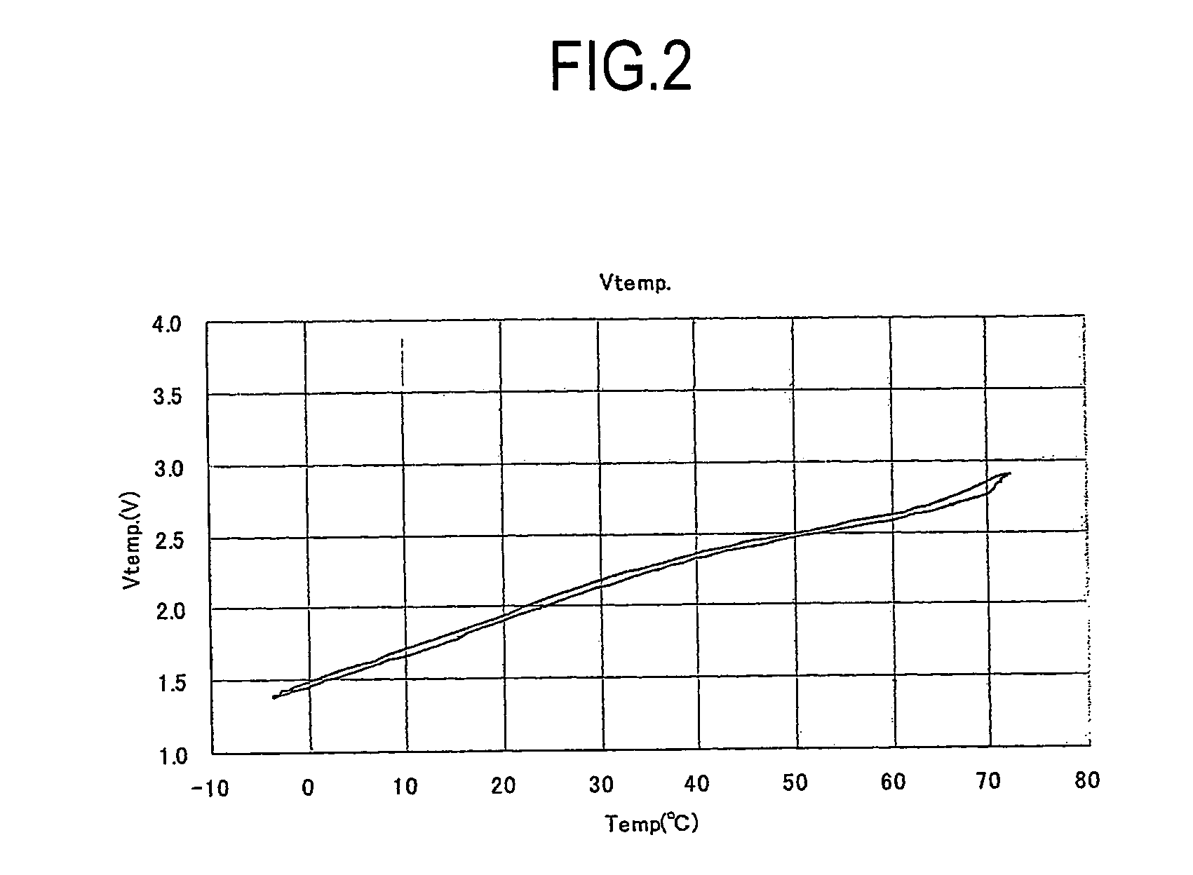
[0027]A control circuit for a thermostatic oven in an oven controlled crystal oscillator according to an embodiment of the present invention to control the thermostatic oven is provided with a temperature sensor circuit, can acquire a voltage which changes according to the ambient temperature of the thermostatic oven in the oscillator, as an internal temperature signal, and can output the internal temperature signal to the outside to be used in frequency control or the like. The control circuit can perform temperature compensation based on the temperature inside the oscillator to thereby make the oscillation frequency of the oven controlled crystal oscillator more stable.

[Oven Controlled Crystal Oscillator According to Embodiment: FIG. 1]

[0028]FIG. 1 is a circuit diagram of a control circuit for a thermostatic oven in an oven controlled crystal osc...


PUM


Abstract

Provided is a control circuit for a thermostatic oven in an oven controlled crystal oscillator, which is capable of further improving stability of an oscillation frequency. A control circuit in which a thermistor whose resistance value changes according to a temperature outputs a signal according to the ambient temperature of the thermostatic oven inside the oscillator, an operational amplifier outputs a signal according to a difference between the output of the thermistor and a reference signal, a power transistor amplifies the output of the operational amplifier, and a heater generates heat based on a collector voltage of the power transistor, is provided with a temperature sensor circuit having a transistor with a base to which the output of the operational amplifier is input. The control circuit outputs a collector voltage of the transistor as an internal temperature signal which changes according to a temperature inside the oscillator.

Description

BACKGROUND OF THE INVENTION[0001]1. Field of the Invention[0002]The present invention relates to a control circuit for a thermostatic oven in an oven controlled crystal oscillator, and more particularly to a control circuit capable of further improving stability of the oscillation frequency of an oven controlled crystal oscillator by performing temperature-based compensation for the oscillation frequency with high accuracy.[0003]2. Description of the Related Art[0004]An oven controlled crystal oscillator (OCXO) has a crystal resonator disposed inside a case whose temperature is maintained constant, and has a stable frequency characteristic which is not easily influenced by an environmental temperature.[0005]A control circuit for a thermostatic oven to be used in an oven controlled crystal oscillator has a heater which heats the thermostatic oven, and a thermistor whose resistance value changes according to the temperature, and controls the temperature in the thermostatic oven to be ...

Claims


Application Information

Patent Timeline
Patent Type & Authority Applications(United States)
IPC IPC(8): H05B1/00
CPCH03L1/028
Inventor ITO, MANABUUCHIDA, TAKESHI
Owner NIHON DEMPA KOGYO CO LTD
Learn More