Flexible pixel element and signal distribution means

a flexible, pixel element technology, applied in static indicating devices, instruments, electroluminescent light sources, etc., can solve the problems such as leds and lcds, need to protect delicate and vulnerable internal electronic components from failure, and increase the cost of use and replacement of more advanced light emitting elements or pixels, so as to improve the longevity of pixel element electronics and improve the sensitivity. , the effect of reducing the cost of us

a flexible, pixel element technology, applied in static indicating devices, instruments, electroluminescent light sources, etc., can solve the problems such as leds and lcds, need to protect delicate and vulnerable internal electronic components from failure, and increase the cost of use and replacement of more advanced light emitting elements or pixels, so as to improve the longevity of pixel element electronics and improve the sensitivity. , the effect of reducing the cost of us

US20090021497A1Active Publication Date: 2009-01-22DAKTRONICS

Image

  • Flexible pixel element and signal distribution means
  • Flexible pixel element and signal distribution means
  • Flexible pixel element and signal distribution means

Examples


Embodiment Construction

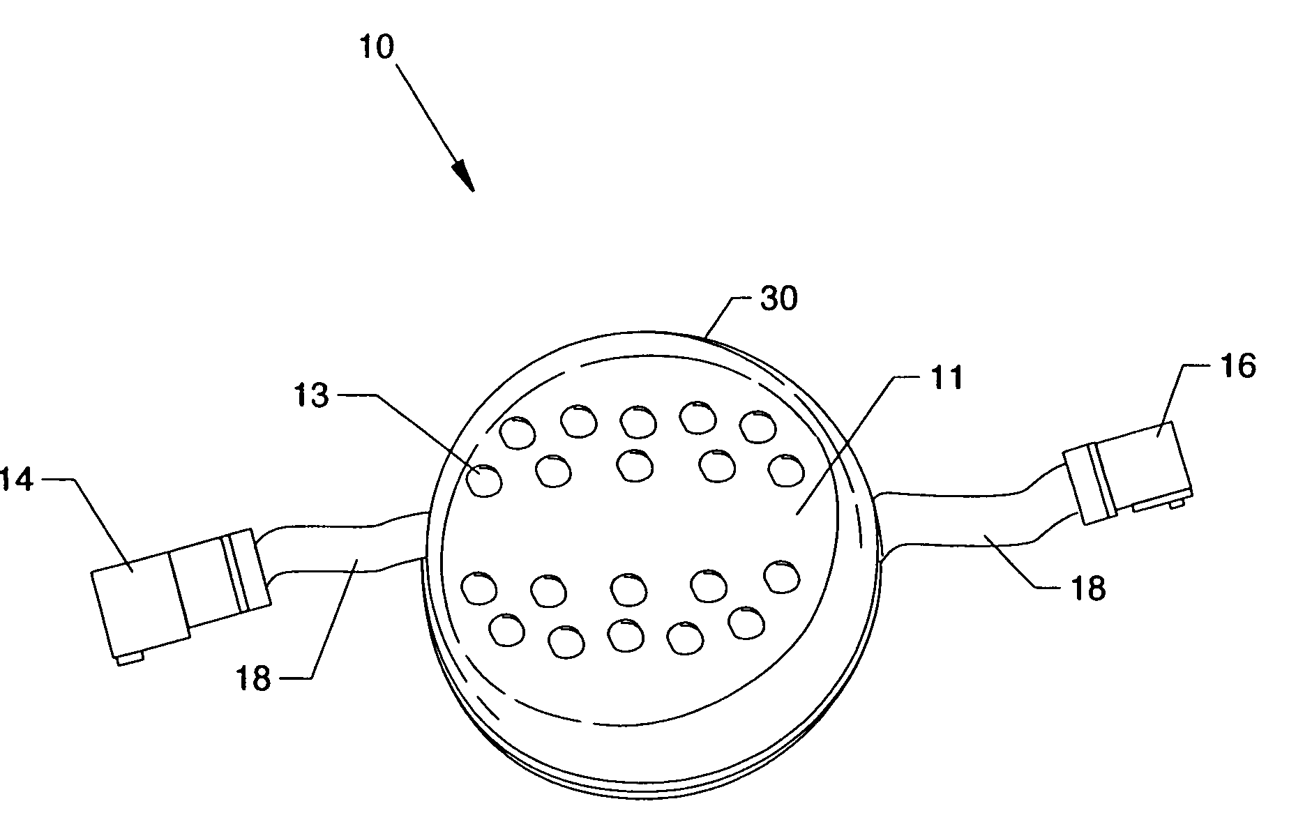
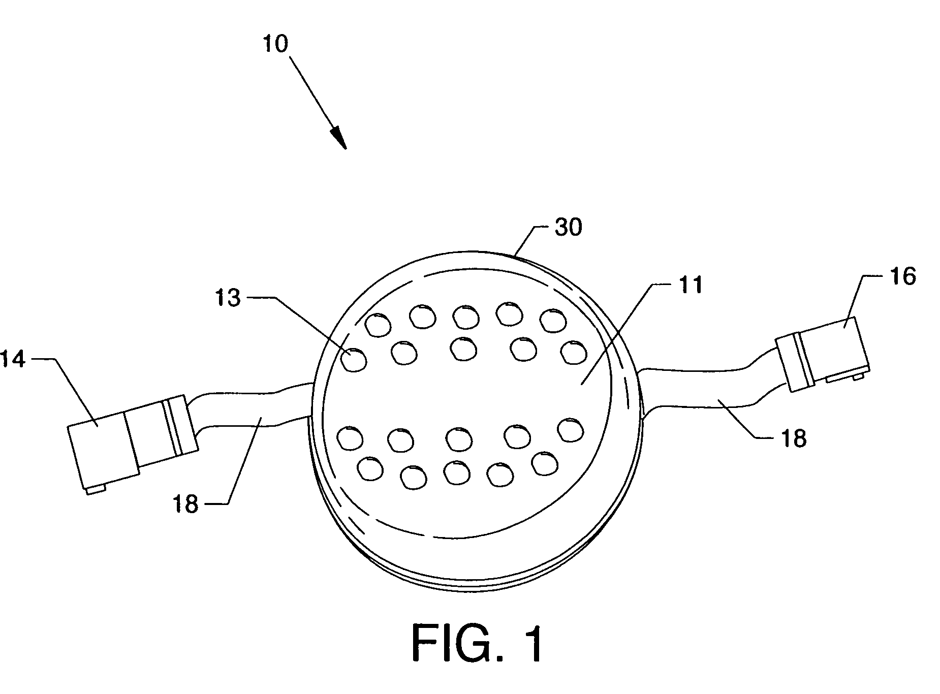
[0046]FIG. 1 is an isometric view of a preferred embodiment of discrete flexible pixel element 10 of the present invention. The flexible pixel element 10 embodies a printed circuit board assembly (not shown) on which various surface mounted electrical components are soldered or mechanically fastened to conductor pads by operative electrical connection including a plurality of light emitting elements 13, top encasement cover 30, input connector 14, output connector 16, and flexible cables 18 embodying in assembly a unitary, self-contained, replaceable module. The light emitting elements 13, or pixels, are illuminated when energized by on-board pixel element drivers (not shown) to produce a visual output in the form of emitted light. In a preferred embodiment, the light emitting elements 13 comprise a plurality of red, green and blue (RGB) colored LEDs.

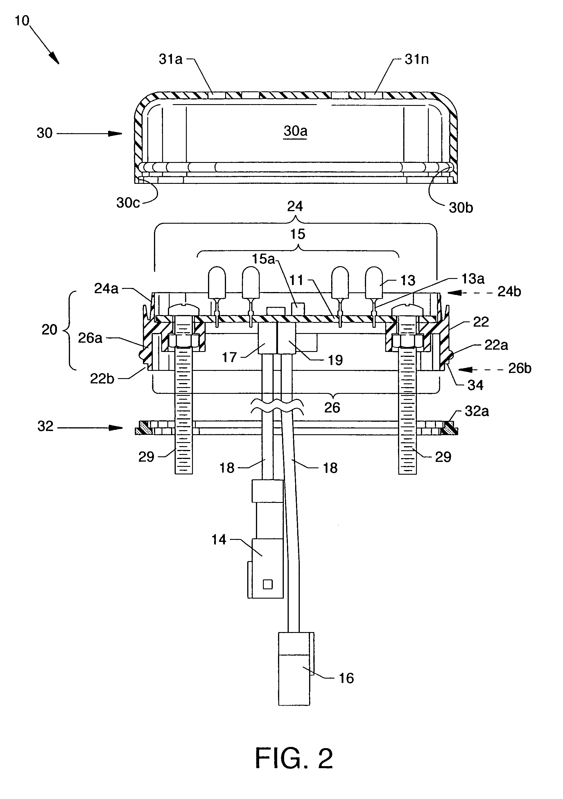
[0047]FIG. 2 is a cross section side view of potting assembly 20, a top encasement cover 30, and a bottom gasket 32. Printed circuit b...


PUM


Abstract

Discrete flexible pixel elements are hermetically sealed from the environment and comprise unitary, self-contained replaceable modules which enable efficient, economical production of large scale, free-form electronic displays, signs and lighting effects for outdoor use. The method and means for producing hermetically sealed discrete flexible pixel elements include encapsulation means, exterior casement means, and cable connector means.

Description

CROSS REFERENCES TO RELATED APPLICATIONS[0001]This application is a continuation-in-part of application Ser. No. 10 / 965,133 filed on Oct. 14, 2004, entitled “Flexible Pixel String Hardware and Method”, which is pending.[0002]This application claims priority from the earlier filed U.S. Provisional Application No. 60 / 926,706 filed Apr. 27, 2007, entitled “Flexible Pixel Assemblies for Mounting on Irregular Surfaces”, and is hereby incorporated into this application by reference as if fully set forth herein.[0003]This application is related to patent application Ser. No. 10 / 965,127 filed on Oct. 14, 2004, entitled “Flexible Pixel String Software and Method”, which is pending.[0004]This application is also related to U.S. utility patent application entitled “Flexible Pixel Element and Signal Distribution Means” (Attorney Docket DAKTRONICS P652), application number to be assigned, filed concurrently herewith, a copy of which is attached and the disclosure of which is incorporated by refe...

Claims


Application Information

Patent Timeline
22 Jan 2009
Publication
US20090021497A1
IPC
G06F3/038
CPC
G06F3/1446; G09G3/32; G09G2300/0426; H05B33/0857; H05B33/0803; H05B33/0815; G09G2370/045; H05B47/00
Inventors
WENDLER, BRETT D.; BRAVEK, ERIC S.