Image forming apparatus

Active Publication Date: 2009-01-22
CANON KK
View PDF4 Cites 9 Cited by
  • Summary
  • Abstract
  • Description
  • Claims
  • Application Information

AI Technical Summary

Benefits of technology

[0018]Accordingly, an object of the present invention is to provide an image forming apparatus which is less expensive, which can suppress a ghost image to maintain satisfactory image quality, which ca

Problems solved by technology

However, since discharge occurs in a minute gap, the photosensitive drum surface is damaged, the amount of wear of the photosensitive drum increases, and the lifetime of the photosensitive drum is shortened.
However, particularly when the photosensitive drum is charged in the direct current method, there arise following problems.
As a result, the potential of the photosensitive drum surface exposed by an exposure device such as a laser also becomes uneven.
On the other hand, when an image is formed repeatedly for a long time, exposure before charge evenly accumulates charge on the photosensitive drum surface, and predetermined photosensitive drum light section potential may not be obtained.
In other words, the sensitivity of the photosensitive drum may become dull.
When the sensitivity of the photose

Method used


Image

  • Image forming apparatus
  • Image forming apparatus
  • Image forming apparatus

Examples


first embodiment

[0033](1) Image Forming Portion

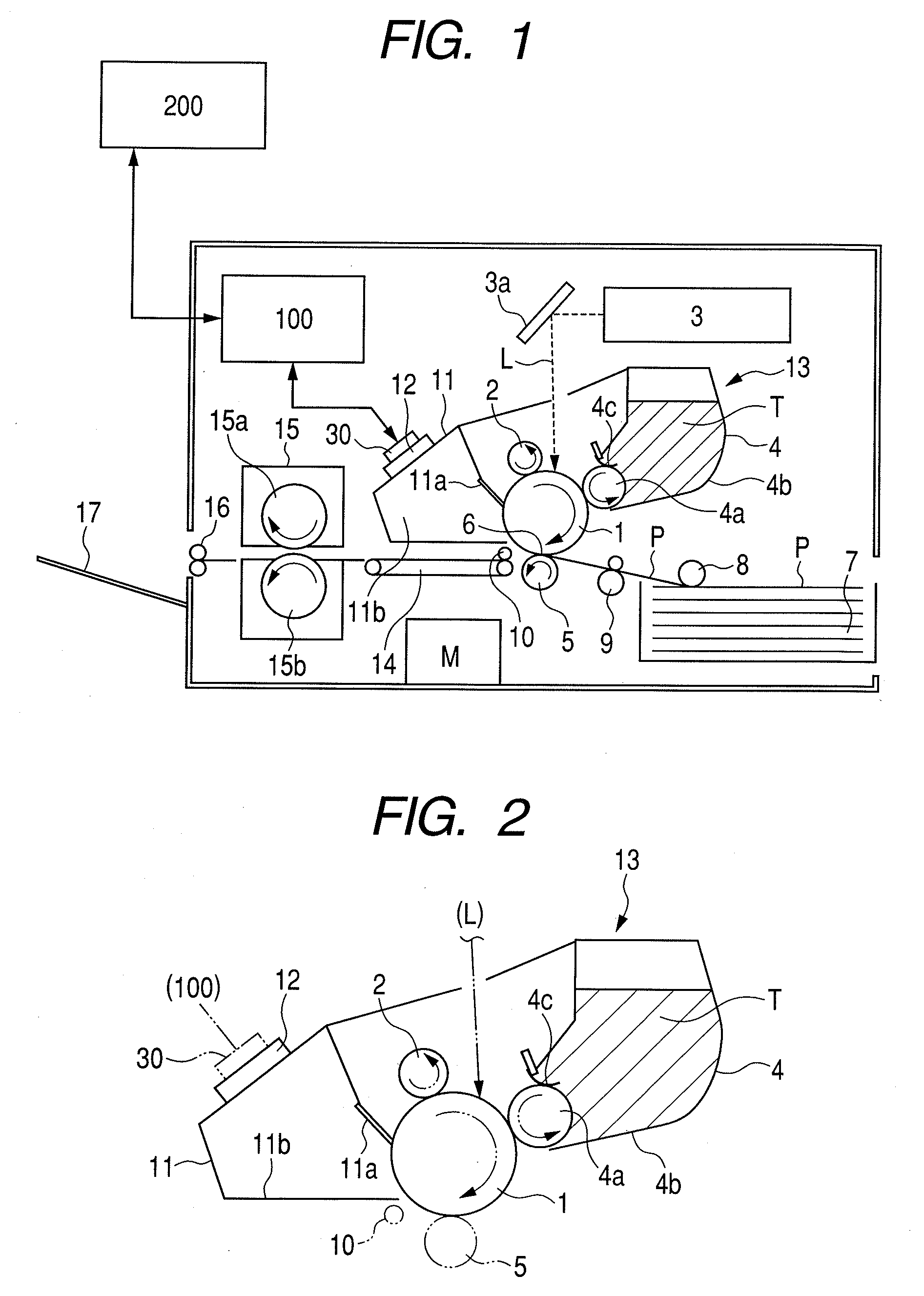
[0034]FIG. 1 is a schematic structural view of an image forming apparatus according to a first embodiment of the present invention. The image forming apparatus is an electrophotographic laser beam printer, and, a series of electrophotographic processes, i.e., charge, exposure, development, transfer, and cleaning are carried out with regard to an electrophotographic photosensitive member of a rotating drum type (hereinafter, referred to as photosensitive drum) 1 as an image bearing member to form an image on a recording material P.

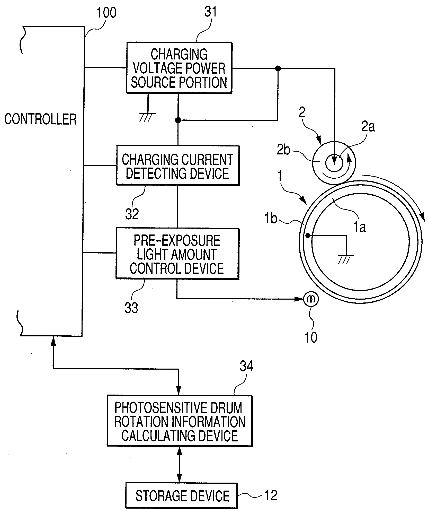
[0035]A controller (engine controller: control circuit portion) 100 carries out system control of the whole image forming apparatus. The controller 100 executes image forming operation based on a print signal which is input from an external host device 200 such as a personal computer, an image reader, or a facsimile machine of the other party. A central processing unit (CPU, not shown) is provided in the controller 100. A seri...

second embodiment

[0091]In the first embodiment of the present invention, the slope α(n) of the charging current when the pre-exposure light amount is changed, that is, the rate of change of the amount of the charging current is used to determine the pre-exposure light amount. However, in the present embodiment, the determination is made using the value of the charging current as it is when the pre-exposure is changed. Similar to the case of the first embodiment of the present invention, during a time period when no image is formed, direct current voltage is applied to the charging roller 2 by the charging voltage applying device to charge the photosensitive drum. Then, exposure is carried out with the exposure light amount of the pre-exposure device for the charged photosensitive drum being changed in a plurality of steps, and regions exposed with the different exposure light amounts are formed on the photosensitive drum. Then, the regions of the photosensitive drum exposed with the different exposu...

third embodiment

[0101]In the second embodiment of the present invention, the value of the charging current as it is when the pre-exposure is changed is used to make the determination, and it is described that the value of Ic(X) has to be changed depending on the film thickness of the photosensitive drum to be used. The second embodiment of the present invention has no problem when the film thickness of the photosensitive drum does not become thinner as the printing proceeds, and when, even if the film thickness becomes thinner, the influence is not so significant and it is not necessary to take the film thickness into consideration. However, when the photosensitive drum is gradually shaved off and the film thickness becomes thinner, and the influence is significant, an appropriate exposure light amount may not be obtained with an apparatus where the film thickness of a photosensitive drum thereof has to be taken into consideration. Therefore, in the present embodiment, the pre-exposure light amount...


PUM


Abstract

An inexpensive image forming apparatus, which can suppress a ghost to obtain an image maintaining satisfactory density and gradations for a long time. The apparatus including an electrophotographic photosensitive member, a contact charger in contact with the photosensitive member for charging the photosensitive member, a charging voltage applying device for applying direct current voltage to the contact charger, a charging current detector for detecting electric current flowing through the contact charger, a pre-exposure device for exposing the photosensitive member to light to remove residual charge on the photosensitive member, and a pre-exposure light amount controller for controlling an exposure light amount of the pre-exposure device in image formation based on the results of detection by the charging current detector when the exposure light amount of the pre-exposure device is changed with direct current voltage applied from the charging voltage applying device to the contact charger during non-image formation.

Description

BACKGROUND OF THE INVENTION[0001]1. Field of the Invention[0002]The present invention relates to an electrophotographic image forming apparatus.[0003]2. Description of the Related Art[0004]Conventionally, as an electrophotographic image forming apparatus, there are an electrophotographic copying machine, an electrophotographic printer (such as an LED printer and a laser beam printer), an electrophotographic facsimile machine, and the like.[0005]In image forming apparatus of these types, a surface of an electrophotographic photosensitive member (hereinafter, referred to as photosensitive drum or drum) is evenly charged by a primary charger and the charged photosensitive drum surface is exposed by an exposure device to form an electrostatic latent image. Then, the electrostatic latent image is developed by a developing device to form a developer image (hereinafter, referred to as a toner image). The toner image is transferred by a transfer device onto a recording material such as a sh...

Claims


Application Information

Patent Timeline
IPC IPC(8): G03G21/00
CPCG03G15/0208G03G2215/025G03G21/06G03G15/0266
Inventor KANAI, RYOSUKEKISHI, YOSUKE
Owner CANON KK
Why Eureka
Try Eureka