Battery pack thermal management system

a battery pack and thermal management technology, applied in the direction of battery/fuel cell control arrangement, lighting and heating apparatus, cell components, etc., can solve the problems of reducing the range of electric cars, the durability and overall life of batteries or cells, and the inability of electric cars to achieve the acceleration, handling, performance, etc., to increase the thermal mass of batteries and reduce the cost of battery or cell maintenance and replacement, the effect of increasing the range and performance of electric vehicles

Inactive Publication Date: 2009-01-22
TESLA INC
View PDF13 Cites 143 Cited by
  • Summary
  • Abstract
  • Description
  • Claims
  • Application Information

AI Technical Summary

Benefits of technology

[0016]One advantage of the present invention may be that it provides a novel and improved thermal management system for a battery pack.
[0017]Still a further advantage of the present invention may be that it provides a thermal management system for use in an electric vehicle.
[0018]Yet another advantage of the present invention may be that it provides a thermal management system for an electric vehicle that will increase the thermal mass of a battery pack, slowing the temperature rise within the battery pack, hence increasing the range and performance of the electric vehicle.
[0019]Still another advantage of the present invention may be that it provides a method of maximizing the longevity of the battery pack by thermally managing the cooling and heating of the pack.
[0020]Yet another advantage of the present invention may be that it provides a thermal management system that reduces the energy storage system cooling demands while driving the electric vehicle hence increasing the vehicles range.
[0021]Yet another advantage of the present invention may be that it provides a thermal management system that will thermally connect each of the cells in the battery pack thereby thermally balancing the entire battery pack while reducing the thermal impedance between the cells of the battery pack.

Problems solved by technology

Furthermore, many of these prior art electrical cars need to be physically large and heavy to accommodate all of these batteries, such that these cars were not capable of achieving necessary acceleration, handling, performance and the extended range needed for an electric car to become a feasible option for public purchase and use.
Many prior art electrical cars that were of normal size and not overly heavy would have a very small range, thus reducing the feasibility for large mass selling of such cars to the consuming public.
Furthermore, many of these prior art electrical cars which use such batteries had problems with protecting the occupants in the vehicle from the high voltage components and high temperatures that emanated from such high voltage components and still provide a car that moved at acceptable speeds comparable to that of a gasoline or diesel internal combustion engine-equipped vehicle.
Many of these prior art electrical cars have had problems with the prior art batteries overheating, thus reducing the range of the electric car and the durability and overall life of the batteries or cells that are part of the battery pack systems within the electric vehicle.
Generally, the batteries or cells arranged within many prior art vehicles operate with high power output which increases the temperature and hence may reduce the longevity of the prior art batteries.
The use of the heavy and high voltage battery systems in prior art electrical cars requires a lot of maintenance to keep the batteries operating due to the high temperatures at which the battery pack systems operated.
However, many of these prior art heat reduction systems for the batteries were not very efficient and did not provide an efficient system for thermally balancing the batteries.
Hence, the prior art system may suffer from overheating or over cooling thus reducing the durability and longevity of the batteries and hence, the range of the electric vehicle.
Generally, in these prior art vehicles if the batteries got too hot it would reduce the batteries longevity and ability to hold a charge, thus reducing the range of the electric vehicle and the overall feasibility for selling such electric cars to the consuming public.

Method used


Image

  • Battery pack thermal management system
  • Battery pack thermal management system
  • Battery pack thermal management system

Examples


Embodiment Construction

)

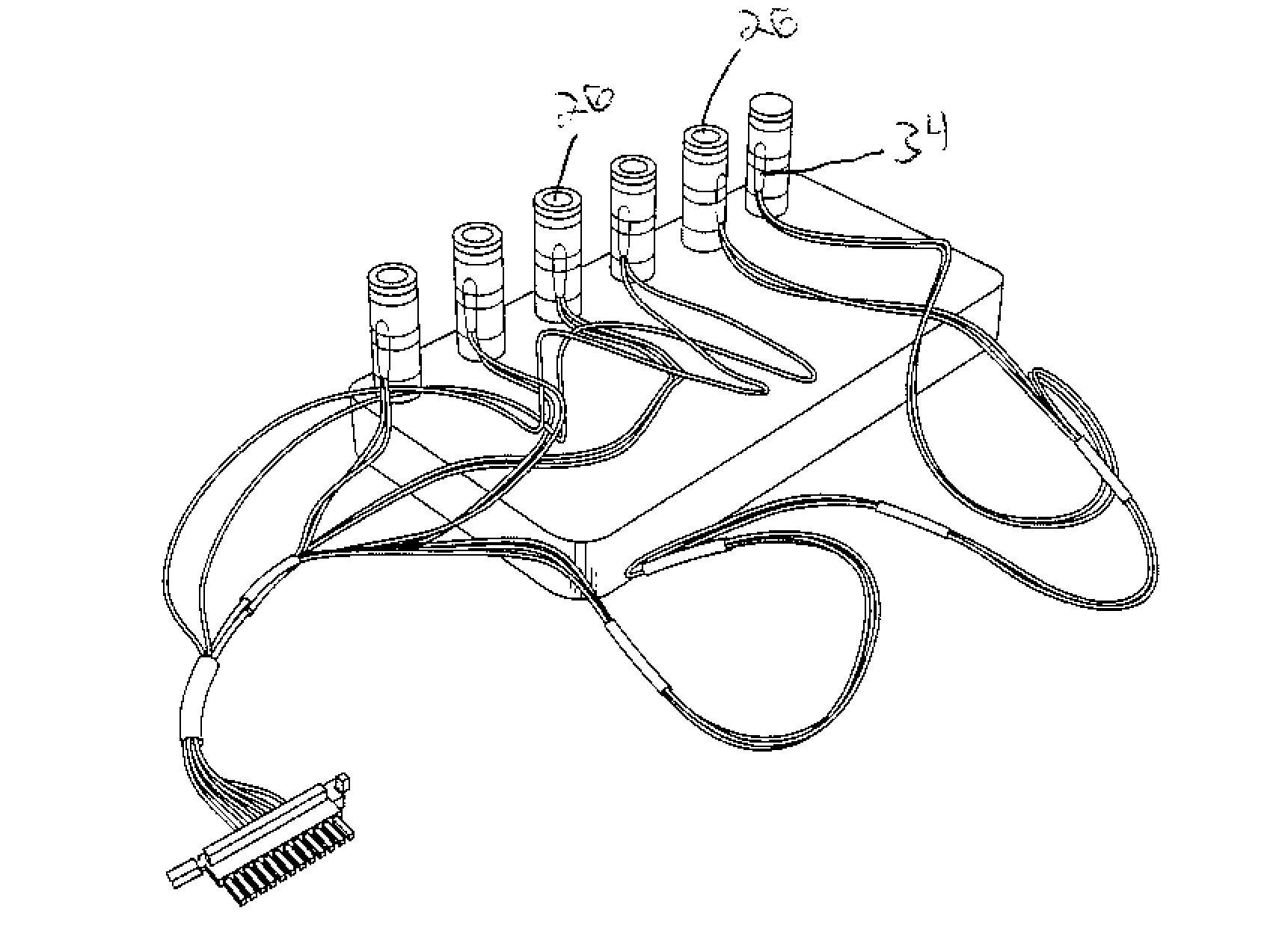
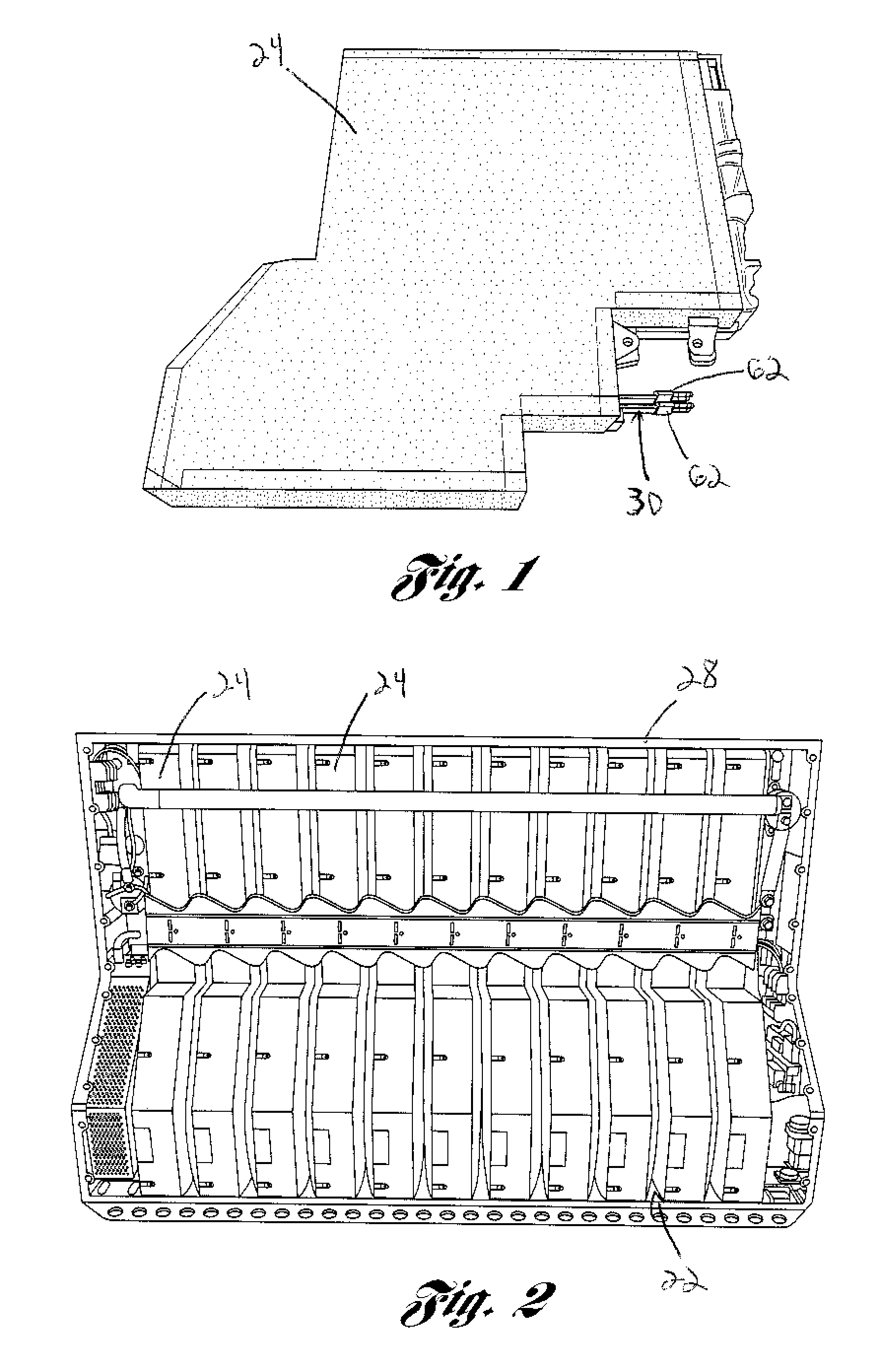
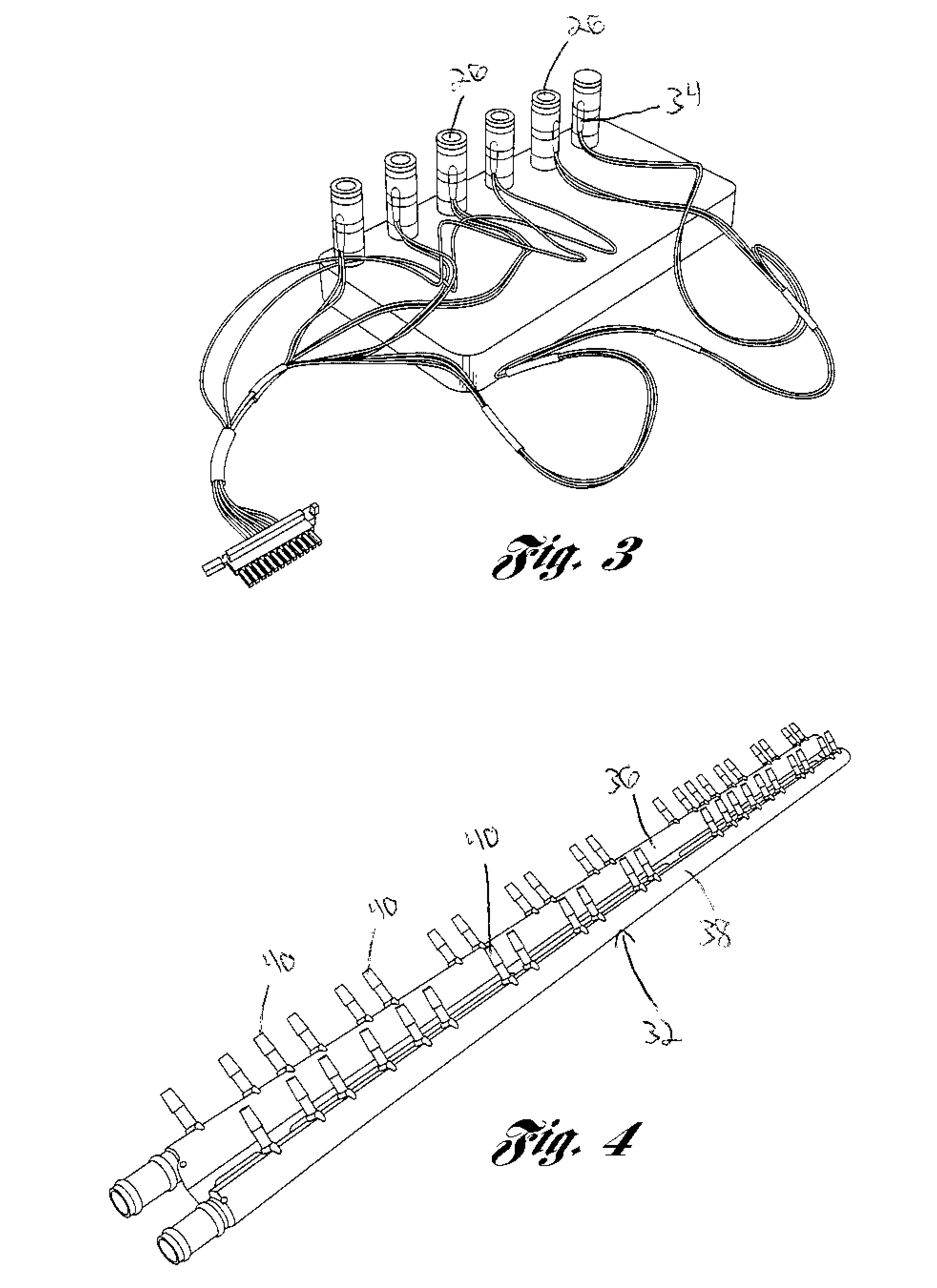
[0035]Referring to the drawings, a battery pack thermal management system 20 for use with an energy storage system (ESS) 22 is shown. The energy storage system or battery pack 22 is generally comprised of a predetermined number of battery modules or sheets 24, a main control and logic PSB, and a 12 volt power supply. In one contemplated embodiment the energy storage system 22 will have eleven battery modules or sheets 24, which are capable of producing approximately 375 volts DC. This nominal voltage will operate an electric vehicle that will be capable of traveling many miles without recharging and is capable of delivering enough power and acceleration to compare favorably with or outperform internal combustion engines. In one contemplated embodiment the ESS 22, will be capable of storing enough energy that the electric vehicle can travel approximately 200 miles without recharging. However, it should be noted that it is also contemplated to have an electric vehicle based on the pr...


PUM

PropertyMeasurementUnit
voltageaaaaaaaaaa
voltageaaaaaaaaaa
temperatureaaaaaaaaaa

Abstract

A battery pack thermal management system for use in an electric car. The battery pack thermal management system includes a plurality of thermistors connected to a plurality of cells of a battery pack. A battery monitor board is connected to the thermistors. The system also includes a manifold and a plurality of cooling tubes connected to the manifold. A tube seal plug is arranged over an end of the cooling tube and an end fitting is arranged on an end of the cooling tube. The thermal management system will cool the battery pack to predetermined temperatures to increase the longevity of the battery pack within the electric vehicle.

Description

BACKGROUND OF THE INVENTION[0001]1. Field of the Invention[0002]The subject invention generally relates to a thermal management system and more particularly relates to a battery pack thermal management system for use in an electric vehicle.[0003]2. Description of Related Art[0004]It is well known in the prior art to use all electric automobiles to provide transportation for occupants. Many of these prior art electric automobiles carry several thousand pounds of nickel metal hydride batteries to achieve a long range electric vehicle for every day use by consumers. Furthermore, many of these prior art electrical cars need to be physically large and heavy to accommodate all of these batteries, such that these cars were not capable of achieving necessary acceleration, handling, performance and the extended range needed for an electric car to become a feasible option for public purchase and use. Many prior art electrical cars that were of normal size and not overly heavy would have a ver...

Claims


Application Information

Patent Timeline
Patent Type & Authority Applications(United States)
IPC IPC(8): H01M10/50B23P15/26H01M2/00B60H1/32H01M50/213
CPCB60L11/1872H01M2/1072H01M10/0525H01M10/5004H01M10/5016H01M10/503Y10T29/49359H01M10/5067H01M10/5077H01M10/5095Y02T10/7005Y02T10/7011Y02T10/705H01M10/5059H01M10/625H01M10/663H01M10/6563H01M10/6568H01M10/6557H01M10/643H01M10/613B60L58/25F28D1/0478Y02E60/10Y02T10/70H01M50/213
Inventor ADAMS, DANIEL T.BERDICHEVSKY, GENECOLSON, THOMAS EVERETTHEBERT, ARTHURKOHN, SCOTTLYONS, DAVIDMENDEZ, NOEL JASONSTRAUBEL, JEFFREY BRIANWEST, DORIANSIMPSON, ANDREW
Owner TESLA INC
Why Eureka
Try Eureka