Fuel filling and waste solution recovery apparatus and fuel vessel

a fuel vessel and waste solution technology, applied in special dispensing means, hydrogen/synthetic gas production, hydrogen, etc., can solve the problem of taking a long time when fuel filling and dehydrogenation product recovery are done separately, and achieve the effect of efficient recovery of dehydrogenation products

Inactive Publication Date: 2009-01-29
HITACHI LTD
View PDF10 Cites 30 Cited by
  • Summary
  • Abstract
  • Description
  • Claims
  • Application Information

AI Technical Summary

Benefits of technology

[0011]According to the present invention, it is possible to provide a fuel filling/waste solution recovery appara

Problems solved by technology

However, there is a problem that it takes much time when dehydr

Method used


Image

  • Fuel filling and waste solution recovery apparatus and fuel vessel
  • Fuel filling and waste solution recovery apparatus and fuel vessel
  • Fuel filling and waste solution recovery apparatus and fuel vessel

Examples


first embodiment

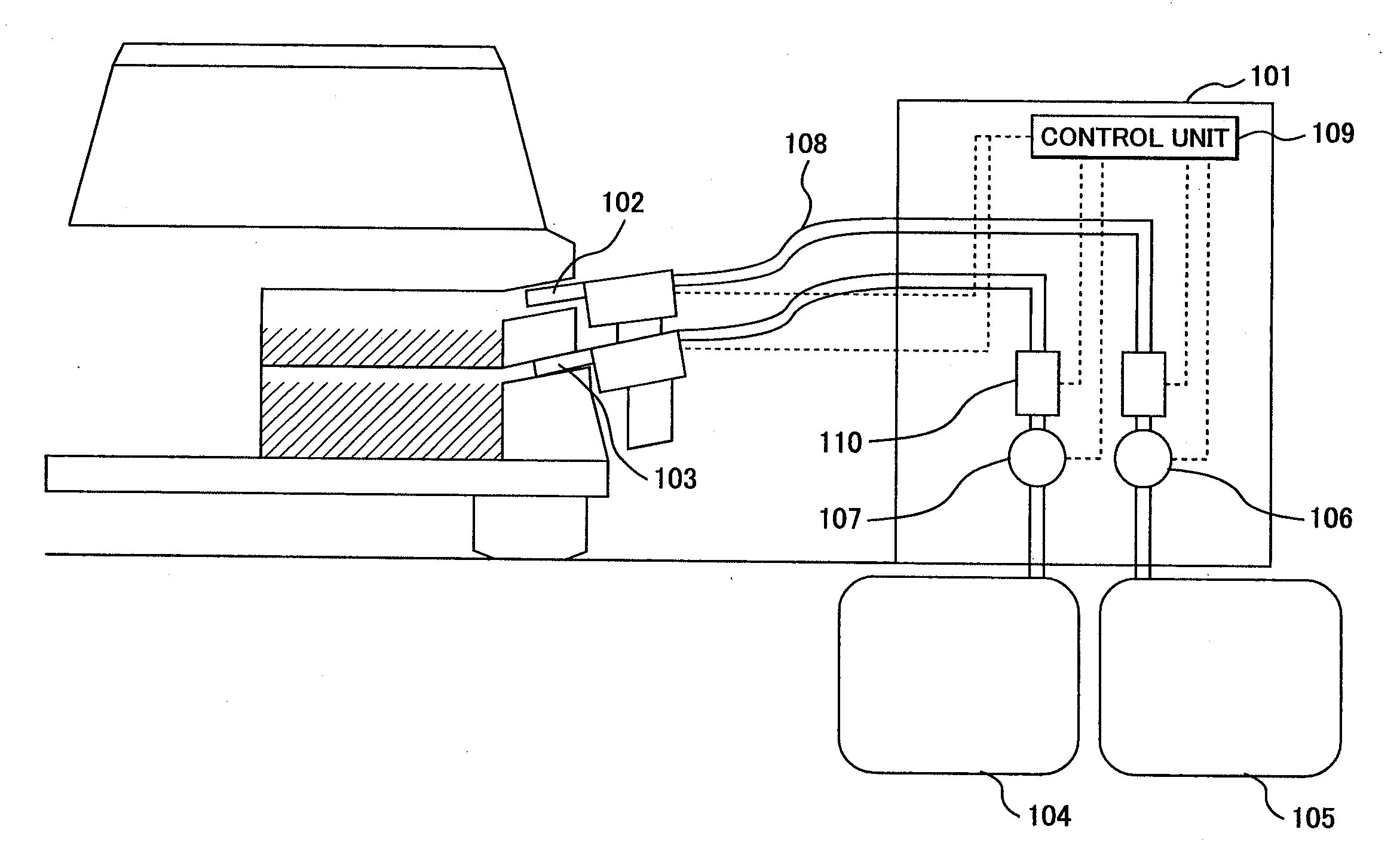
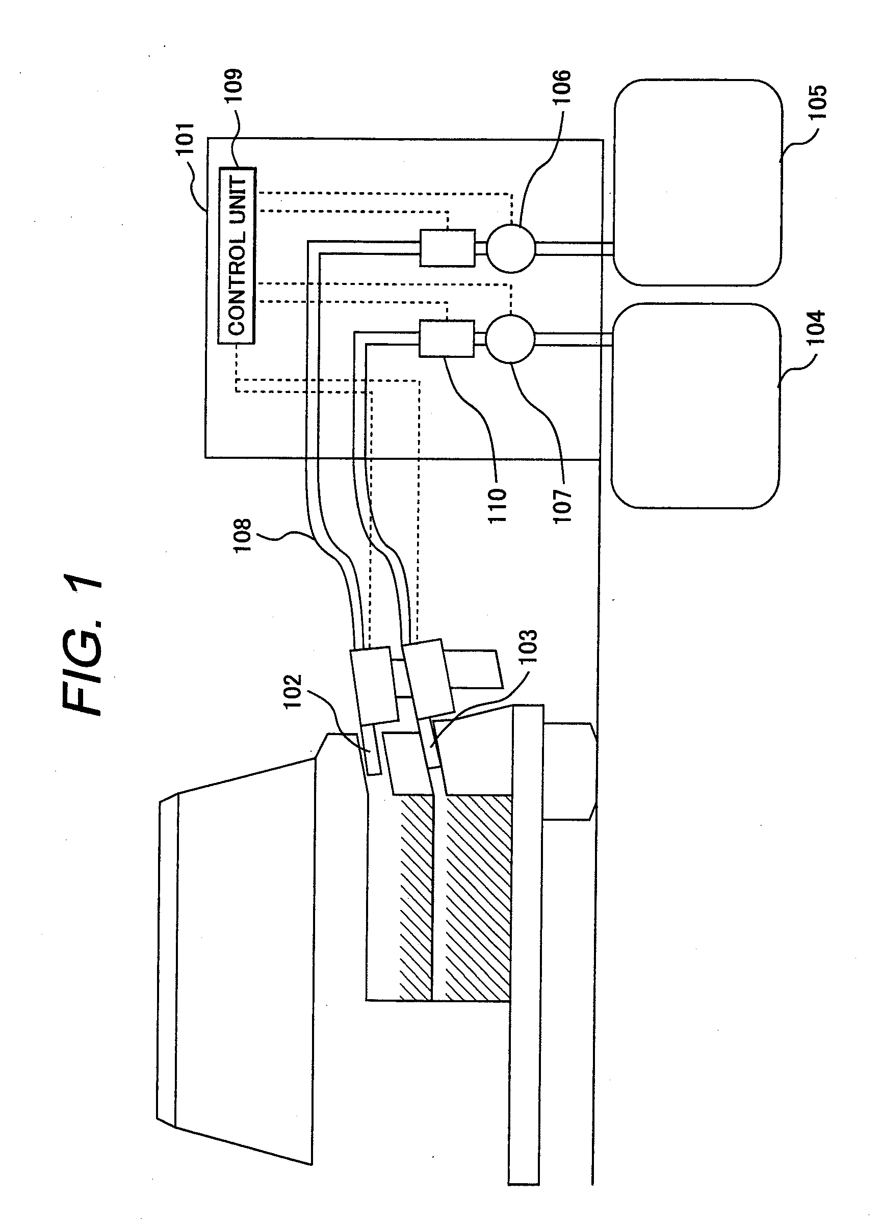
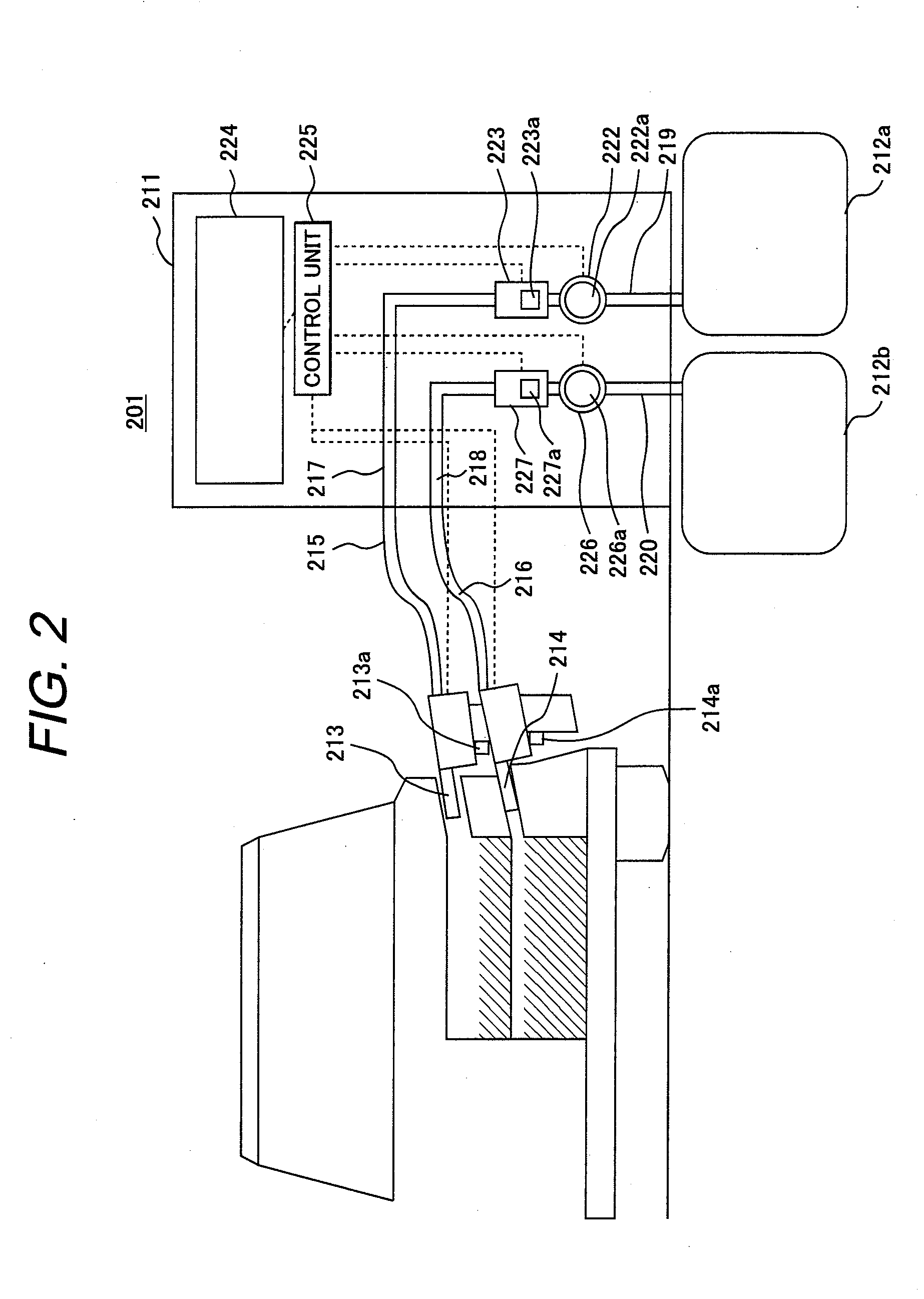
[0060]FIG. 2 is a schematic view showing an organic hydride dispenser for cars according to this embodiment. As shown in FIG. 2, a fuel filling apparatus 201 has a housing 211 which supplies fuel such as gasoline to the fuel tank (not shown) of a car, fuel tank 212a for supplying fuel to the housing, a waste solution tank 212b, a fuel filling nozzle 213, and a waste solution recovery nozzle 214. A fuel filling hose 215 and a waste solution hose 216 which are connected with the fuel filling nozzle 213 and waste solution recovery nozzle 214, are drawn from a side face of the housing of the fuel filling apparatus 201.

[0061]As a customer's car arrives at a fuel filling station, a worker at the fuel filling station puts the fuel filling nozzle 213 into the fuel filling port in the car's fuel tank (to which fuel is to be supplied).

[0062]The housing 211 houses a fuel filling duct 217 and a waste solution duct 218 continuously connected with the fuel filling hose 215 and waste solution hose...

second embodiment

[0079]Next, an embodiment in which a data storage device is attached to the apparatus in the first embodiment to load data as necessary to calculate total fuel cost or the like will be described.

[0080]FIG. 4 is a schematic view of an organic hydride dispenser for cars which is equipped with a data storage device 228 according to this embodiment. Here, in addition to the configuration in the first embodiment, the data storage device 228 is electrically connected with the control unit 225 so that the CPU can access data. The stored data includes fuel unit price (yen / L), waste solution unit price (yen / L), hydrogen content (m3 / L), waste solution treatment unit price (yen / L), and carbon tax (yen / L). Individual data pieces are managed on a daily basis by ID and tabularized, for example, as shown in FIG. 5.

[0081]For example, in the apparatus according to the present invention, if 35 liters of hydride is supplied and the same volume of waste solution is recovered on Dec. 15, 2010, the CPU w...

third embodiment

[0083]This embodiment is an example of a fuel filling / waste solution recovery apparatus in which an ultraviolet spectral sensor is attached to the tip of the waste solution nozzle of the fuel filling / waste solution recovery apparatus according to the present invention to permit quantification of the volume of hydride in the waste solution.

[0084]When the fuel filling / waste solution recovery apparatus shown in FIG. 4 recovers waste solution from a machine which uses fuel, the recovered waste solution is likely to contain unreacted fuel. FIG. 6 shows the average conversion rate of methylcyclohexane which varies according to temperature. When the reaction environment is heated to 300° C. or more, virtually 100% conversion of methylcyclohexane takes place, emitting hydrogen. However, when the reaction environment is below 300° C., the conversion rate rapidly declines. At start of the machine which uses fuel, the temperature does not reach 300° C. and even at 300° C. or more, depending on...


PUM

PropertyMeasurementUnit
Pressureaaaaaaaaaa
Volumeaaaaaaaaaa
Areaaaaaaaaaaa

Abstract

Recovery of dehydrogenation product must be done separately from supply of hydrogen fuel. However, there is a problem that it takes much time when dehydrogenation product recovery and fuel filling are done separately. A fuel filling/waste solution recovery apparatus includes measuring means to measure a volume of supplied fuel and a volume of recovered waste solution by measuring flow rates of solutions passing through a fuel filling nozzle and a recovery nozzle or piping, and a display which shows the volume of supplied fuel and the volume of recovered waste solution which are measured by the measuring means.

Description

CROSS REFERENCE TO RELATED APPLICATION[0001]This application is a Continuation-in-Part of International Patent Application PCT / JP2007 / 051078 filed on Jan. 24, 2007, the entire contents of which are incorporated herein by reference.CLAIM OF PRIORITY[0002]The present application claims priority from Japanese Patent Application No. 2006-046098 filed on Feb. 23, 2006, and International Patent Application PCT / JP2007 / 051078 filed on Jan. 24, 2007, the contents of which are hereby incorporated by reference into this application.TECHNICAL FIELD[0003]The present invention relates to a fuel filling / waste solution recovery apparatus and a fuel vessel.BACKGROUND ART[0004]Since hydrogen storage materials have properties similar to those of gasoline, some of the existing infrastructures for petroleum fuels can be used for them and also since their explodability is lower than other hydrogen fuels, they are hydrogen fuels which can be supplied at low cost with safety. However, one feature of hydrog...

Claims


Application Information

Patent Timeline
IPC IPC(8): B67D5/08B67D5/22B67D7/08B67D7/22
CPCB60K2015/03473F17C2270/0178C01B3/501C01B2203/0277C01B2203/041C01B2203/048C01B2203/1041C01B2203/1047C01B2203/1052C01B2203/1058C01B2203/1064C01B2203/107C01B2203/1082C01B2203/1252F17C11/005H01M8/04089H01M8/04208H01M8/065H01M8/0662Y02E60/321Y02E60/324Y02E60/50F17C2205/058F17C2221/011F17C2221/012F17C2221/08F17C2223/0123F17C2223/036F17C2250/032F17C2250/034F17C2250/036F17C2250/0426F17C2250/0443F17C2250/0473F17C2250/0495F17C2250/0621F17C2250/0694F17C2260/025F17C2265/065F17C2270/0139C01B3/26Y02E60/32Y02P90/45
Inventor NOUJIMA, MASAFUMIITABASHI, TAKEYUKIISHIKAWA, TAKAOKANEMOTO, HIROSHIYAMADA, SHINJI
Owner HITACHI LTD
Why Eureka
Try Eureka