Connection structure and method of connecting field coil and lead wires in vehicle alternator

a technology of connecting structure and lead wire, which is applied in the direction of magnetic circuit rotating parts, magnetic circuit shape/form/construction, manufacturing stator/rotor bodies, etc., can solve the problems of difficult automation of the assembly process of covering wires with insulators, difficult to manage the quality of products, and inability to determine the disconnect from the outsid

Active Publication Date: 2009-01-29
ERAE AMS CO LTD
View PDF8 Cites 21 Cited by
  • Summary
  • Abstract
  • Description
  • Claims
  • Application Information

AI Technical Summary

Benefits of technology

[0021]Accordingly, the present invention has been made keeping in mind the above problems occurring in the prior art, and the present invention is directed to provide a new conceptual connection structure and a method of connecting field coils and lead wires in a vehicle alternator, which can solve the conventional problem in which ultrasonic welding, which is used to fasten the lead wires of a slip ring and the field coils of a rotor coil, which are connected to respectively correspond to each other, causes lead wires to be released, thus making it difficult to observe whether the lead wires are disconnected.

Problems solved by technology

However, there are problems in that an electrical short circuit may occur in the vehicle alternator 100 due to the impact that is transmitted to the lead wires 118a by the vibration, which occurs due to the ultrasonic welding, which cause a lead wire 118a to be released and to come into contact with the 115, and in that, when the alternator 100 is rotated at high speed during the travel of a vehicle, a defect, such as a short circuit, which occurs in the alternator 100 due to disconnection of the lead wires 118a, may occur.
Furthermore, there is a problem in that it is difficult to manage the quality of a product in an early stage because the structure of fastening the lead wires 118a and the field coils 117a by ultrasonic welding is formed such that whether the lead wires 118a are disconnected cannot be determined from the outside.
In this case, it is difficult to automate the assembly process of covering wires with insulator tubes, and it is also very difficult to assemble a field coil 117a in each insulator tube while maintaining accurate dimensions.
In addition, if movement of the field coils 117a in such insulator tubes is not completely prevented, it may become a potential defect at high speeds.

Method used


Image

  • Connection structure and method of connecting field coil and lead wires in vehicle alternator
  • Connection structure and method of connecting field coil and lead wires in vehicle alternator
  • Connection structure and method of connecting field coil and lead wires in vehicle alternator

Examples


Embodiment Construction

[0052]Embodiments of the present invention are described in detail with reference to the accompanying drawings below.

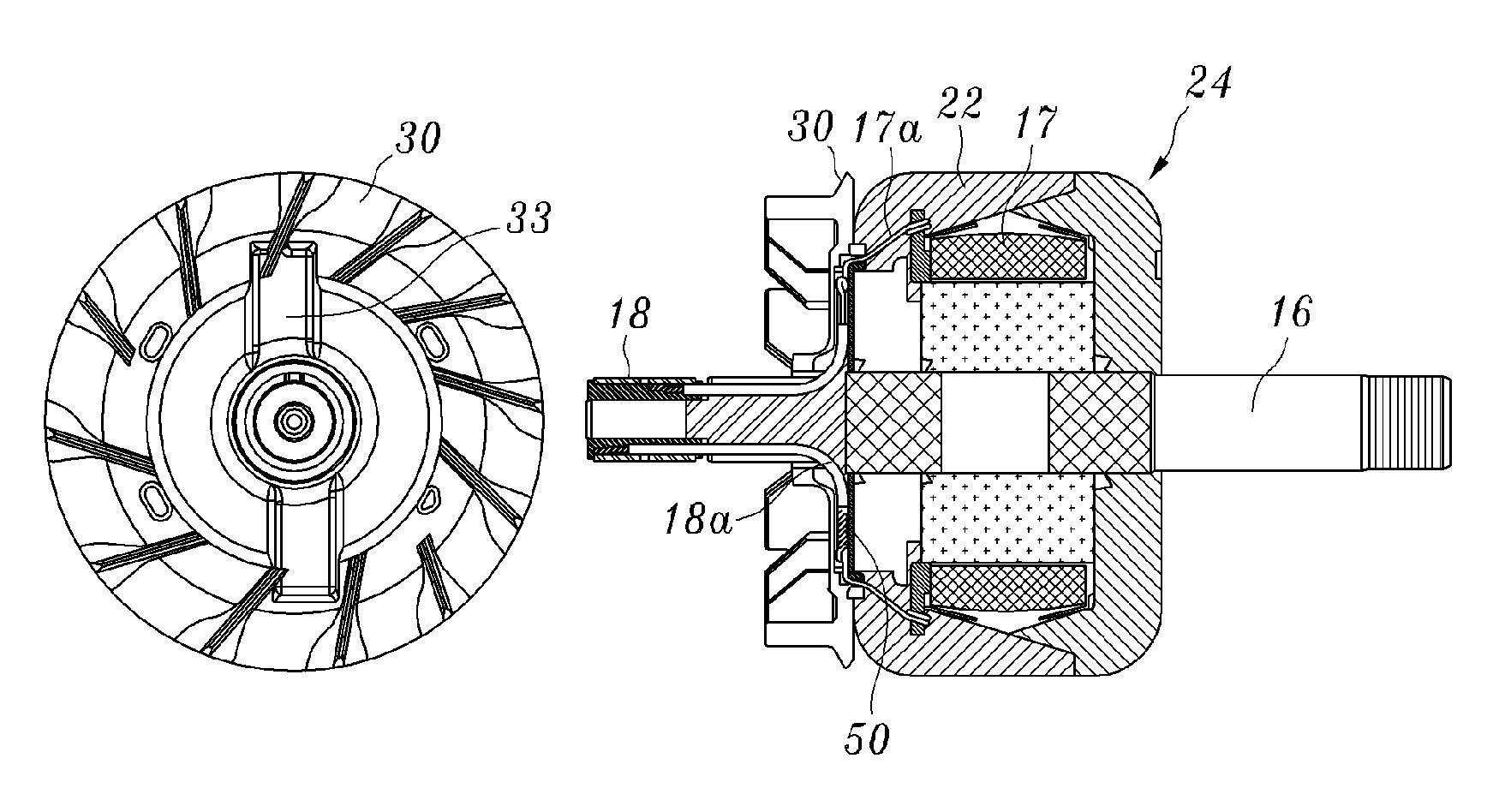
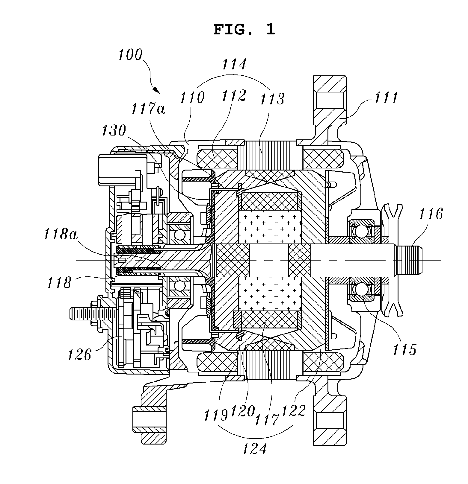
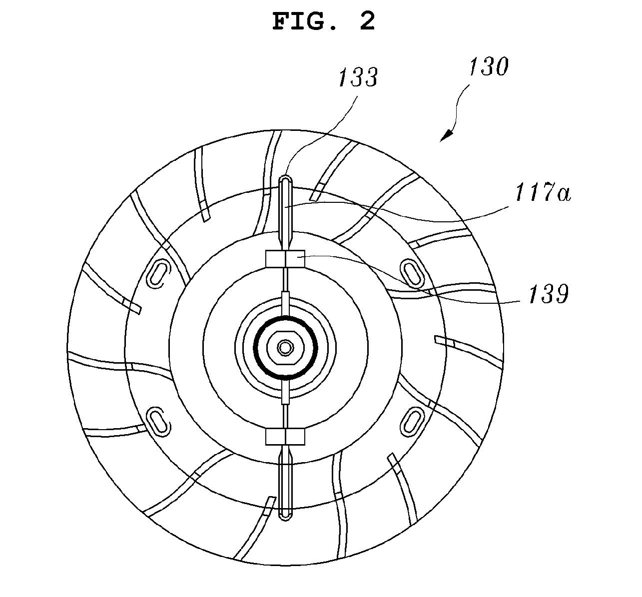
[0053]FIG. 4 is a sectional view schematically showing a vehicle alternator according to an embodiment of the present invention, FIG. 5 is a front perspective view schematically showing a rear fan according to an embodiment of the present invention, FIG. 6 is a rear perspective view schematically showing the rear fan according to the embodiment of the present invention, FIG. 7 is a front perspective view schematically showing a rotor insulator according to an embodiment of the present invention, FIG. 8 is a rear perspective view schematically showing the rotor insulator according to the embodiment of the present invention, FIG. 9 is a side sectional view and a front view of a rotor assembly, to which a connection structure between field coils and lead wires according to an embodiment of the present invention is applied, FIGS. 10A to 10F are side sectional views and fr...


PUM

PropertyMeasurementUnit
depthaaaaaaaaaa
lengthaaaaaaaaaa
heightaaaaaaaaaa

Abstract

A connection structure and a connection method of connecting field coils and lead wires in a vehicle alternator. The connection structure includes a rotor assembly, a rear fan, and a rotor insulator. The rotor assembly includes a rotor shaft, a spool bobbin, and rotor segments. In the connection structure, a soldering or welding process is performed on twisted parts, which are formed by twisting field coils and lead wires around each other, the twisted parts are bent in the guide pockets of the rotor insulator, epoxy is applied to the outer surfaces of the twisted parts and the inner surfaces of guide pockets, and the rear fan is coupled to the front of the rotor insulator so that the inner surfaces of the protrusion hubs of the rear fan are in close contact with the guide pockets of the rotor insulator.

Description

BACKGROUND OF THE INVENTION[0001]1. Field of the Invention[0002]The present invention relates generally to a vehicle alternator and, more particularly, to a connection structure and a method of connecting field coils and lead wires in a vehicle alternator, in which an electrical connection structure between the lead wires of a slip ring and the field coils of a rotor assembly is achieved by performing epoxy curing in the space between hubs, which protrude from the front surface of a rear fan, and guide pockets, so that a work process is simplified and, thus, costs can be reduced because the process of assembling an insulator tube with the field coil is eliminated and, in addition, a defect rate attributable to the simplification of the work process can be minimized because a welding process, a soldering process, a bending process and an epoxy coating process are performed on twisted parts, which are formed on the field coils and the lead wires in the guide pockets of a rotor insulat...

Claims


Application Information

Patent Timeline
Patent Type & Authority Applications(United States)
IPC IPC(8): H02K15/10
CPCH02K9/06H02K13/02Y10T29/49012H02K15/12H02K15/0075H02K15/0068H02K3/28
Inventor AN, SANG-CHULHA, IL-WOOYOU, JAE PIO
Owner ERAE AMS CO LTD
Why Eureka
Try Eureka