Display apparatus

a technology of display apparatus and display screen, which is applied in the field of display screen, can solve the problems of increasing manufacturing costs, affecting the quality of display screen, so as to increase the amount of correction data, and increase the storage area

Inactive Publication Date: 2009-01-29
SONY CORP
View PDF3 Cites 13 Cited by
  • Summary
  • Abstract
  • Description
  • Claims
  • Application Information

AI Technical Summary

Benefits of technology

[0009]The abovementioned video signal correction according to the amount of light intercepted by the variable iris demands a plurality of types of correction data depending on the magnitude of the amount of light interception. In this case, a finer uniformity correction accord

Problems solved by technology

As a result, the data amount may become extremely large, necessitating an extremely large storage area.
This needs a large number of storage elements, thus raising manufacturing costs and the like.
This issue is also not limited to the projection display apparatus, but the same is true for the direct-view type

Method used


Image

  • Display apparatus
  • Display apparatus
  • Display apparatus

Examples


Embodiment Construction

[0022]A preferred embodiment of the present invention will now be described in detail with reference to the accompanying drawings.

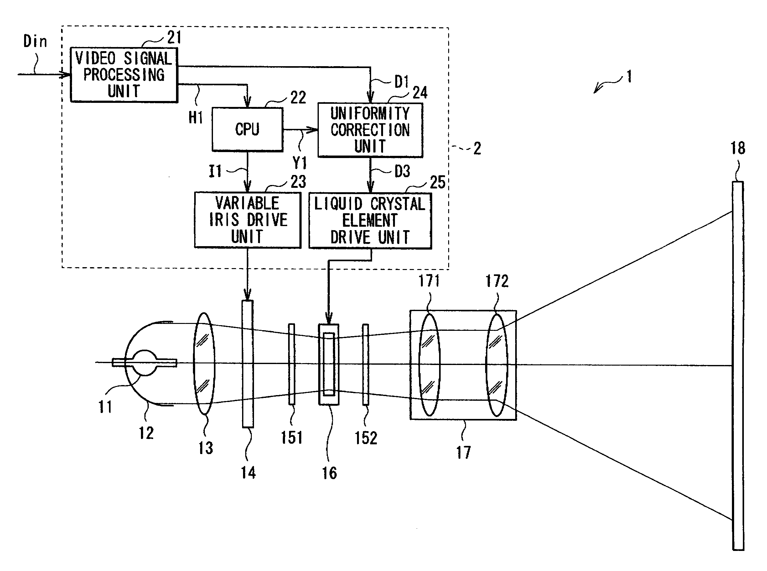
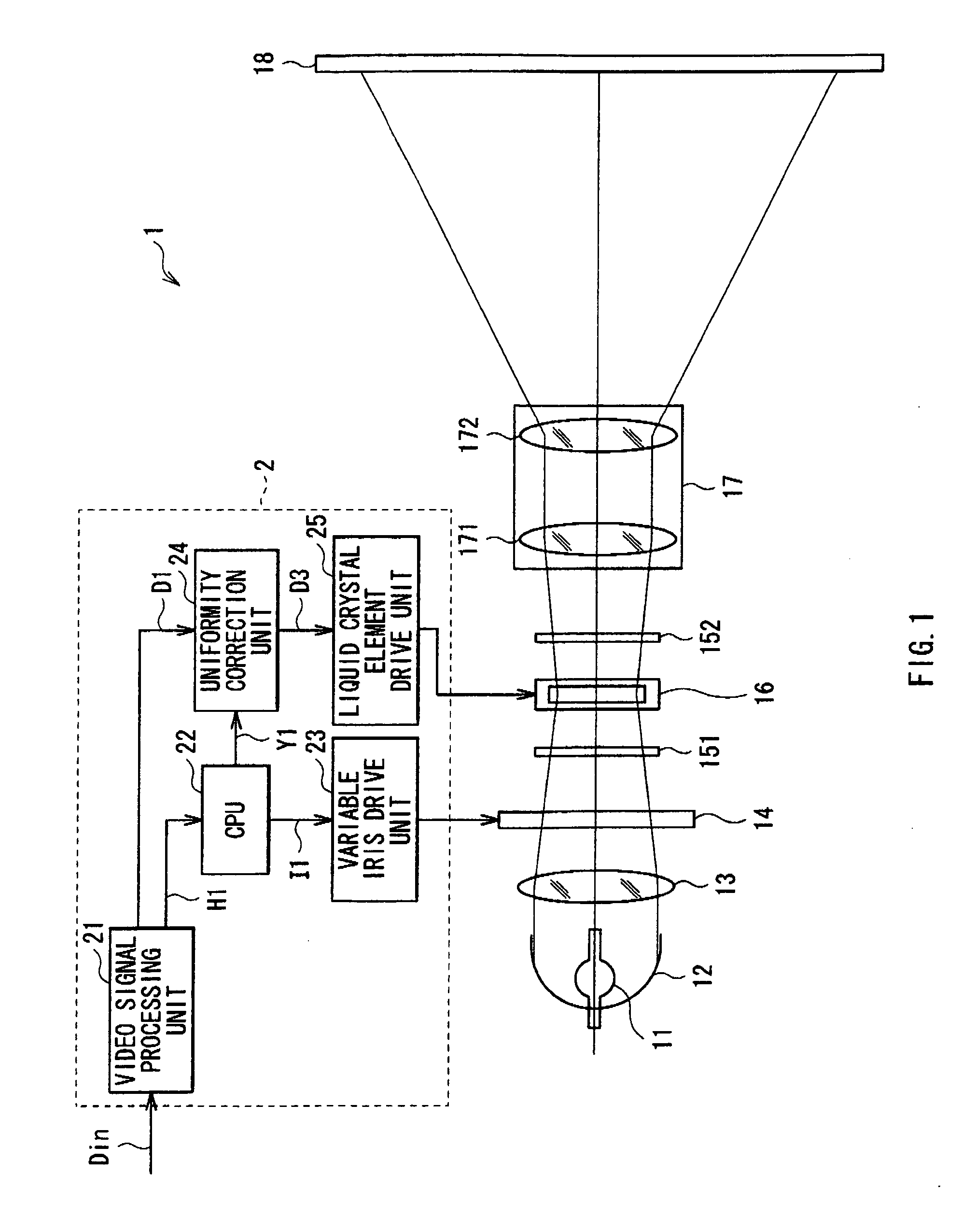
[0023]FIG. 1 shows the entire configuration of a display apparatus (a liquid crystal projector 1) according to an embodiment. The liquid crystal projector 1 is for displaying an image based on an input video signal Din supplied from the outside, and configured by a light source 11, a reflecting mirror 12, an illumination optical system 13, a variable iris 14, a polarizer 151, a liquid crystal element 16, an analyzer 152, a projection lens unit 17, a screen 18, and a controller 2 to control the variable iris 14 and the liquid crystal element 16 based on the input video signal Din.

[0024]The light source unit 11 emits white light containing red light (R), blue light (B) and green light (G) necessary for color image display, and is configured by, for example, a halogen lamp, a metal halide lamp or a xenon lamp.

[0025]The reflecting mirror 12 reflects the light...


PUM


Abstract

A display apparatus includes: a light source; spatial light modulation device for modulating light emitted by the light source based on a video signal; intensity distribution adjusting means for changing an angle-dependent intensity distribution of an incident light in response to luminance factor in the video signal, the intensity distribution adjusting means being arranged ahead of or behind the spatial light modulation device; and correction means for correcting the video signal in accordance with an intensity distribution adjusted by the intensity distribution adjusting means, and supplying a corrected video signal to the spatial light modulation device, in which the correction means has a plurality of correction tables each corresponding to a predetermined intensity distribution, generates a mixed correction value by mixing correction values in the plurality of correction tables at a mixing ratio determined by an individual intensity distribution, and corrects the video signal by using the mixed correction value.

Description

CROSS REFERENCES TO RELATED APPLICATIONS[0001]The present invention contains subject matter related to Japanese Patent Application JP 2007-192173 filed in the Japanese Patent Office on Jul. 24, 2007, the entire contents of which being incorporated here by reference.BACKGROUND OF THE INVENTION[0002]1. Field of the Invention[0003]The present invention relates to a display apparatus applicable to a liquid crystal projector and the like.[0004]2. Description of the Related Art[0005]Projection display apparatuses such as liquid crystal projectors have been widely used which are configured to display an image by subjecting the light entered into a spatial light modulation device to spatial modulation, and emitting the modulated light, and then collecting and projecting the emitted light in accordance with an electric signal supplied to the spatial light modulation device. The projection display apparatus generally has a lamp and a condensing mirror as light sources, and an illumination opt...

Claims


Application Information

Patent Timeline
IPC IPC(8): G02F1/13
CPCG09G3/002G09G3/3406G09G3/3611G09G2320/0233G09G2320/0285H04N9/3197G09G2320/0646G09G2360/16H04N9/3155H04N9/3182G09G2320/0633
Inventor MIYAUCHI, JUNHIRAI, KOJI
Owner SONY CORP
Why Eureka
Try Eureka