Analyzer

a technology of analyzer and a meter, applied in the field of analyzer, can solve the problems of large scale change in design and difficulty in improving analytical precision, and achieve the effects of improving analytical precision, high-precision analysis, and increasing the degree of photothermal conversion

Inactive Publication Date: 2009-01-29
KOBE STEEL LTD
View PDF7 Cites 16 Cited by
  • Summary
  • Abstract
  • Description
  • Claims
  • Application Information

AI Technical Summary

Benefits of technology

[0008]The present invention has been achieved in consideration of the above-mentioned problem, and an object is to provide an analyzer capable of easily improving analytical precision.
[0011]Therefore, the apparatus is capable of efficiently analyzing the impurity concentration in the liquid with high precision. Further, the apparatus is capable of analyzing the impurities online without stopping the passage of the liquid through the line.
[0013]According to the present invention, the component to be analyzed is exited by irradiation with the exciting light to cause photothermal conversion, and a temperature change in the sample which generates heat due to the photothermal conversion is measured as a change in refractive index of the sample on the basis of the measuring light before and after the transmission through the sample, thereby permitting quantitative analysis of the component to be analyzed.
[0014]Namely, the analyzer according to the present invention is capable of improving analytical precision by increasing the degree of the photothermal conversion, and thus even when the concentration of the component to be analyzed is low, high-precision analysis can be performed by increasing the intensity of the exciting light which induces the photothermal conversion.
[0015]Therefore, according to the present invention, analytical precision can be easily improved by a relatively simple method such as a method of increasing the intensity of exciting light.

Problems solved by technology

However, the detector of Patent Document 1 directly detects absorbance for analyzing a component and thus has difficulty in improving analytical precision.
However, such a change in design becomes a large scale and is restricted by limitations on the space in an apparatus and the like.

Method used


Image

  • Analyzer
  • Analyzer
  • Analyzer

Examples


first embodiment

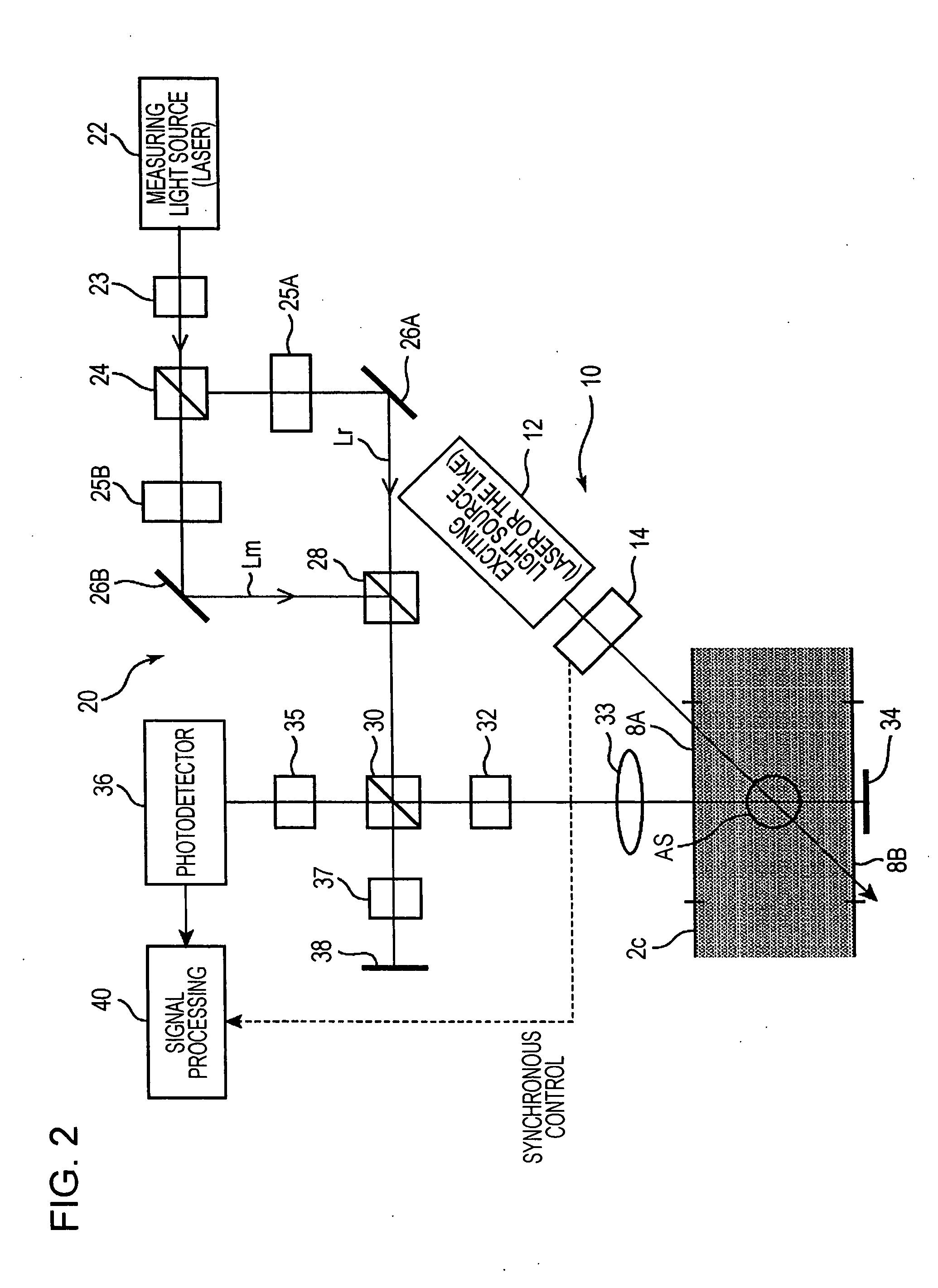
[0028]the present invention will be described with reference to FIGS. 1 and 2.

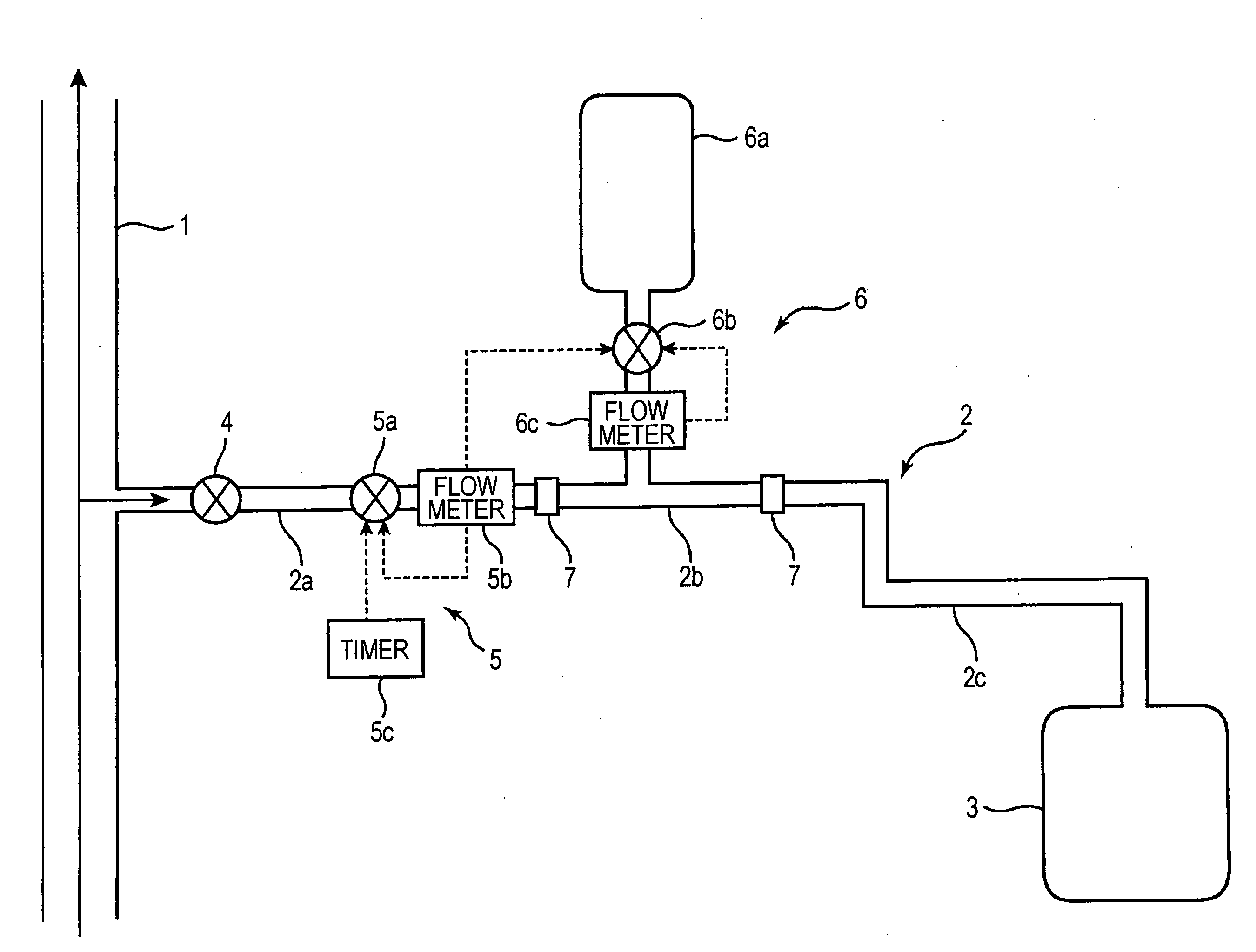
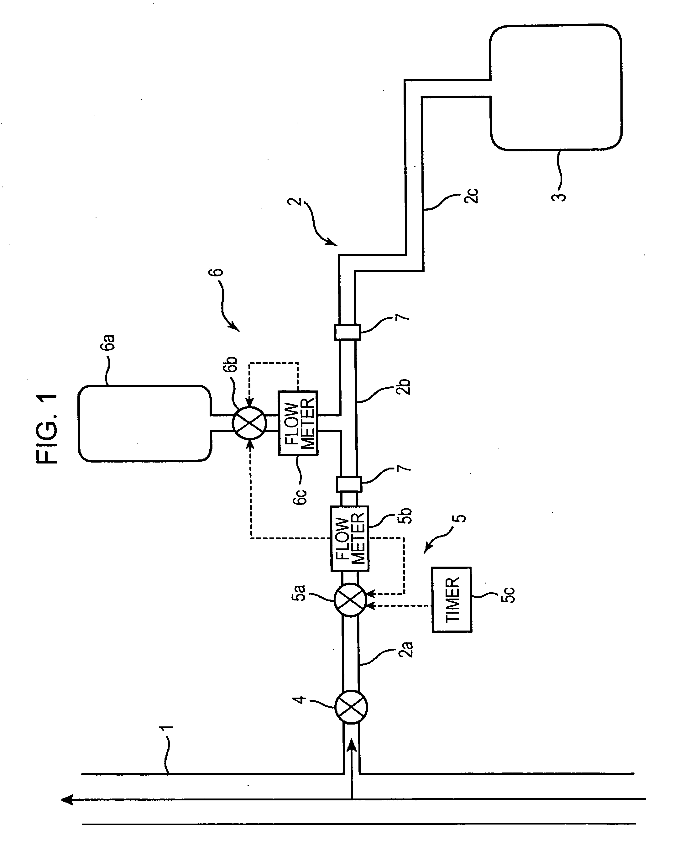
[0029]FIG. 1 shows the entire configuration of an impurity analyzer according to this embodiment. The analyzer is adapted to analyze impurities contained in a liquid (e.g., ultrapure water or process water) flowing through a predetermined line 1 and includes a branch line 2 branched from the line 1 and a tank 3 connected to the end of the branch line 2. The branch line 2 has an inlet portion 2a, a coloring portion 2b, and an absorption spectrometric portion 2c in that order from the upstream side.

[0030]The inlet portion 2a is provided with a main valve 4 and a flow rate control portion 5. The main valve 4 is opened and closed for switching on and off introduction of the liquid into the branch line 2. The flow control portion 5 is adapted to control the flow rate of the liquid flowing through the branch line 2.

[0031]Specifically, the flow control portion 5 is provided with a valve device 5a including an ele...


PUM

PropertyMeasurementUnit
absorption wavelengthaaaaaaaaaa
phase changeaaaaaaaaaa
concentrationaaaaaaaaaa

Abstract

The concentration of impurities contained in ultrapure water or press water can be efficiently analyzed with high precision. A portion of a liquid to be measured is introduced into an absorption spectrometric portion 2c from a predetermined line. The liquid is irradiated with exciting light Le from an exciting light irradiation system 10, and a measurement objet region AS in which a photothermal effect of the impurities in the liquid is produced by the irradiation is irradiated with measuring light Lm from a measuring light irradiation system 20. A change in phase of the measuring light Lm is detected by a predetermined optical system and a photodetector 36, and the impurity concentration in the liquid is determined on the basis of the change in phase.

Description

TECHNICAL FIELD[0001]The present invention relates to an analyzer for analyzing a specified component among components contained in a sample.BACKGROUND ART[0002]There have been known analyzers each including a detection portion for detecting a specified component in a sample.[0003]This type of detectors includes a detector for detecting absorbance of a specified component (for example, a liquid chromatographic detector of Patent Document 1).[0004]However, the detector of Patent Document 1 directly detects absorbance for analyzing a component and thus has difficulty in improving analytical precision.[0005]Namely, in order to directly detect absorbance, an intensity ratio (transmittance) before and after transmission through a sample is required, and thus it is necessary to set a long optical path for light transmitted through the sample so that an intensity ratio to be detected is increased for improving analytical precision.[0006]In order to extend the optical path, it is necessary ...

Claims


Application Information

Patent Timeline
Patent Type & Authority Applications(United States)
IPC IPC(8): G01N21/31G01N1/20
CPCG01N21/00G01N21/171G01N21/45G01N21/85G01N2030/746G01N33/18G01N2021/1712G01N2021/8557G01N21/94
Inventor TAKAHASHI, EIJIKATAYAMA, RYOKANNAKA, MASATOTAKAMATSU, HIROYUKI
Owner KOBE STEEL LTD
Why Eureka
Try Eureka