Optical waveguide ring resonator with an intracavity active element

a technology of intracavity active elements and optical waveguides, which is applied in the field of optical waveguides and photonic circuits, can solve the problems of inability to achieve sufficient coupling,

Active Publication Date: 2009-01-29
HEWLETT-PACKARD ENTERPRISE DEV LP
View PDF99 Cites 29 Cited by
  • Summary
  • Abstract
  • Description
  • Claims
  • Application Information

AI Technical Summary

Problems solved by technology

Sufficient coupling may be difficult to achieve in many cases.
Another challenge of integrating an intracavity active optical element into an optical ring resonator is choosing appropriate materials for the integrated structure.
Specifically, an ideal or highly desirable material for realizing the optical waveguide may be less than ideal for or even incompatible with an implementation of the intracavity active element.
For example, while silicon may be a relatively attractive material (e.g., low cost) for realizing and implementing the optical waveguide of the optical resonator, silicon is an indirect band gap material and, as such, is not particularly well-suited for constructing active optical elements.

Method used


Image

  • Optical waveguide ring resonator with an intracavity active element
  • Optical waveguide ring resonator with an intracavity active element
  • Optical waveguide ring resonator with an intracavity active element

Examples


Embodiment Construction

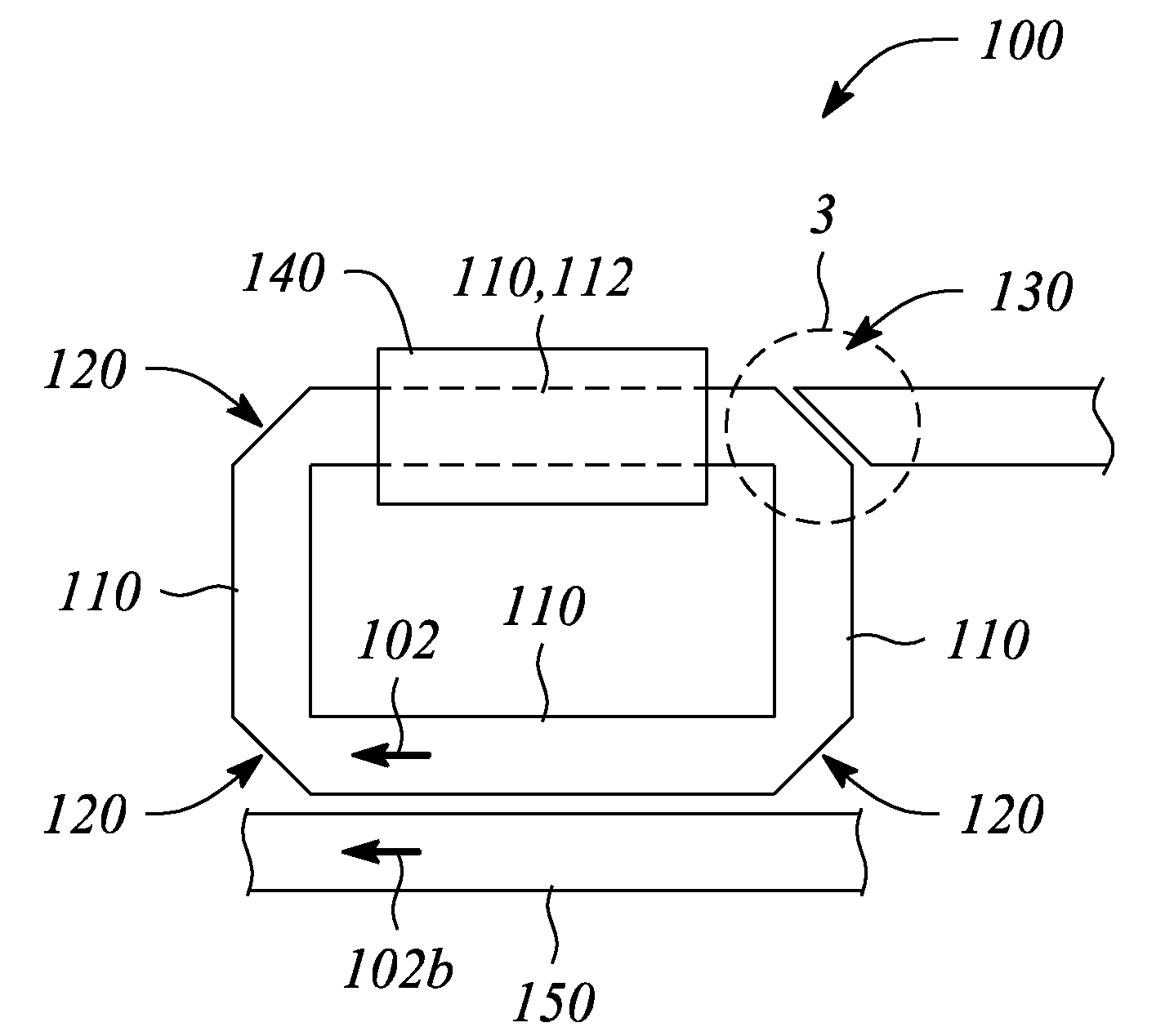
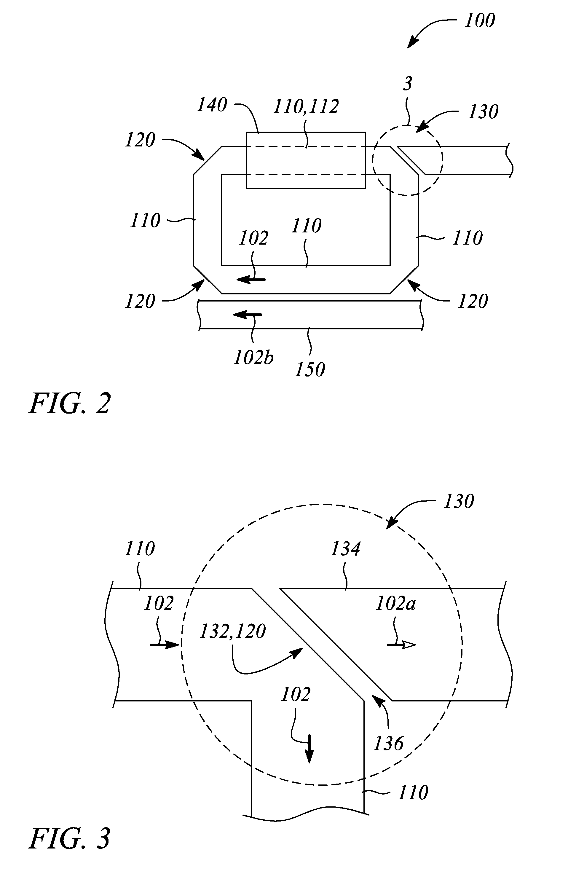
[0026]Embodiments of the present invention employ optical waveguide segments and total internal reflection (TIR) mirrors to realize an optical resonator having low optical loss. In particular, the optical resonator of the present invention is a closed loop, ring-shaped resonant structure that supports a propagating optical signal within the closed loop. In various embodiments of the optical resonator according to the present invention, one or more input / output ports (I / O ports) are provided. The I / O port(s) facilitate one or both of introducing to and extracting from the optical resonator the propagating optical signal or a portion thereof.

[0027]Further, the optical resonator provides active optical properties. In particular, an intracavity active element that is integrated with and optically coupled to the optical resonator. Through the optical coupling, the intracavity active element influences (e.g., generates, amplifies or modulates) an optical signal propagating within the opti...


PUM


Abstract

An optical resonator, a photonic system and a method of optical resonance employ optical waveguide segments connected together with total internal reflection (TIR) mirrors to form a closed loop. The optical resonator includes the optical waveguide segments, an intracavity active element coupled to a designated one of the optical waveguide segments, the TIR mirrors and a photo-tunneling input / output (I / O) port. The photo-tunneling I / O port includes one of the TIR mirrors. The method includes propagating and reflecting the optical signal, or a portion thereof, in the optical resonator, transmitting a portion of the optical signal through the I / O port, and influencing the optical signal. The photonic system includes the optical resonator with optical gain and a source of an optical signal.

Description

CROSS-REFERENCE TO RELATED APPLICATIONS[0001]The present invention is related to patent application of Wu et al., entitled “Optical Waveguide Ring Resonator with Photo-Tunneling Input / Output Port” (Attorney Docket No. 200701489), filed concurrently herewith, which is incorporated by reference herein in its entirety.STATEMENT REGARDING FEDERALLY SPONSORED RESEARCH OR DEVELOPMENT[0002]N / ABACKGROUND[0003]1. Technical Field[0004]The invention relates to optical waveguides and photonic circuits. In particular, the invention relates to optical waveguide resonators used in photonic devices and systems.[0005]2. Description of Related Art[0006]An optical ring resonator generally comprises a segment or segments of optical waveguide arranged as a closed loop or ring. The closed loop forms a resonant cavity. Such ring resonators have a variety of important uses in photonic devices and systems. In particular, the optical ring resonator may serve as an active photonic device having one or more ac...

Claims


Application Information

Patent Timeline
Patent Type & Authority Applications(United States)
IPC IPC(8): G02B6/125G02B6/36H01S3/083
CPCG02B6/125H01S5/1071H01S5/026G02B2006/12104
Inventor WU, WEIWANG, SHIH-YUANTAN, MICHAEL RENNE TYFATTAL, DAVID A.SANTORI, CHARLES M.BEAUSOLEIL, RAYMOND G.
Owner HEWLETT-PACKARD ENTERPRISE DEV LP
Why Eureka
Try Eureka