
Magnetic resonance imaging device

a magnetic resonance imaging and device technology, applied in the field of magnetic resonance imaging technique, can solve the problems of low spatial resolution and hard to say that the structure is sufficiently extracted, and achieve the effect of high accuracy and correction of brightness distortion of images

Inactive Publication Date: 2009-01-29
HITACHI MEDICAL CORP
View PDF2 Cites 26 Cited by
  • Summary
  • Abstract
  • Description
  • Claims
  • Application Information

AI Technical Summary

Benefits of technology

[0024]According to the present invention, the images are connected after the positional distortion and the brightness distortion of the images have been corrected. Therefore, it is possible to obtain an image without any displacements or brightness unevenness at the joint of the images after being connected. In addition, since the correction of the brightness distortion is performed before correcting the positional distortion, the positional distortion can be corrected with a high accuracy.
[0025]According to the present invention, the positional distortion and the brightness distortion of the morphological image and the functional image are corrected, by using the corrective information for the positional distortion and brightness distortion as to the morphological image. Therefore, it is possible to obtain a composite image without any displacement in position and brightness, even when the morphological image and the functional image are superimposed one on another, and in addition, when the images are connected in the multi-station imaging.

Problems solved by technology

Since the functional image is obtained by imaging the functions, generally it is hard to say that the structure is sufficiently extracted.
Moreover, in many cases, spatial resolution tends to be low due to a difficulty in imaging.

Method used


Image

  • Magnetic resonance imaging device
  • Magnetic resonance imaging device
  • Magnetic resonance imaging device

Examples


first embodiment

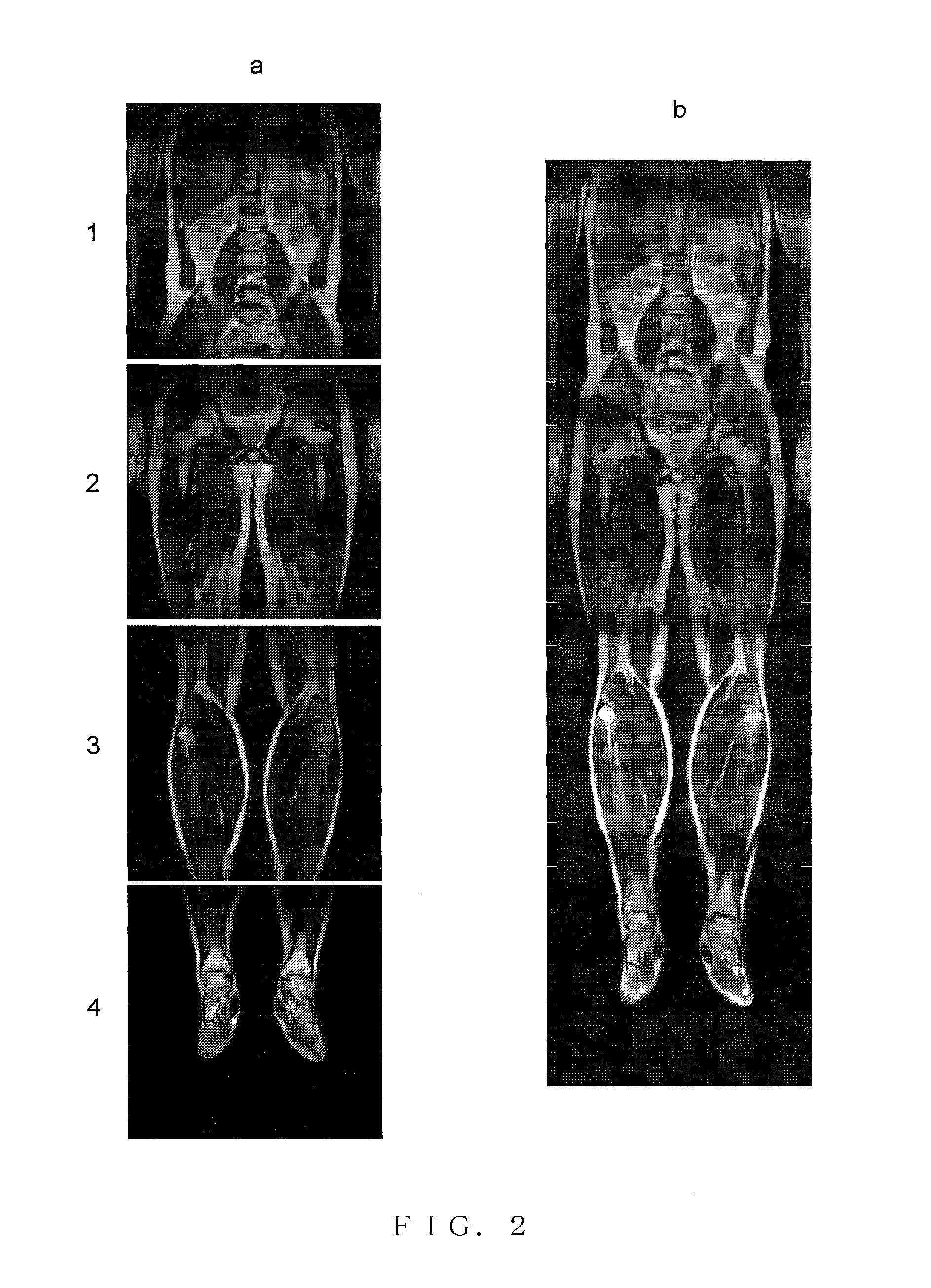
[0043]Next, an image forming method according to the aforementioned MRI apparatus will be explained. In the present embodiment, there will be explained a case where the imaging is performed by a multi-station imaging system. The multi-station imaging system is used when a field of view (FOV) is larger than an imaging available area, such as imaging of a whole body. According to this system, an image is taken after dividing the whole body into areas (stations), and images of respective stations are synthesized to produce a whole body image. Here, one example will be explained, that is, under the condition that the FOV of one-time imaging is set to 42 cm and the imaging is performed at every movement of the table by 35 cm, four times of imaging in total are performed with three times of table movement.

[0044]FIG. 2 illustrates images that are taken by using the high-speed spin echo imaging with 256×256 pixels. FIG. 2a illustrates four images from the shoulder to the feet of a human, an...

second embodiment

[0065]Next, the present invention will be explained. In the present embodiment, corrective information obtained from a morphological image is used to correct brightness distortion and positional distortion of a functional image. Here, an explanation will be made, taking a diffusion-weighted image as an example of the functional image, in which a tumor can be highlighted. Cells in the tumor are densely arranged and the diffusion coefficient thereof is small compared to other tissues. Therefore, in the diffusion-weighted image, signals are measured at a higher level. By applying this method to a whole body imaging in multi-station, a whole body screening for finding a tumor is possible. A typical imaging method for imaging the diffusion-weighted image is the diffusion-weighted echo planar. In the diffusion-weighted image, however, most of the area other than the tumor generates a low signal. Therefore, it is not possible to correct the brightness distortion and the positional distorti...


PUM


Abstract

The magnetic resonance imaging apparatus includes a control unit for controlling a pulse sequence that applies an RF magnetic field and a magnetic field gradient to a subject placed in a static magnetic field and detects a magnetic resonance signal generated from the subject, and a calculation unit for processing the signal, and the control unit performs the process including the steps of; (1) obtaining first images at different positions in a first direction, (2) obtaining images after the first images are subjected to correction of brightness distortion, (3) obtaining images after the images as to which the brightness distortion has been corrected are further subjected to correction of positional distortion, and (4) synthesizing by a weighting calculation, overlapping areas of the images, after the positional distortion thereof has been corrected. According to this magnetic resonance imaging apparatus, the positional distortion and the brightness distortion can be corrected upon connecting the images, in the multi-station imaging.

Description

TECHNICAL FIELD[0001]The present invention relates to a magnetic resonance imaging technique.BACKGROUND ART[0002]A magnetic resonance imaging (MRI) apparatus is a medical image diagnostic apparatus that applies an RF magnetic field and a magnetic field gradient to a subject placed in a static magnetic field, and measures a signal generated from the subject according to a nuclear magnetic resonance, so that an image is created. In the MRI apparatus, a size of an area that can be a target for imaging at one time is limited to around 40 cm. This is because a homogeneous region of the static magnetic field has a shape of sphere with a diameter of around 45 cm. Therefore, if there is a requirement to take an image of wider area such as imaging a whole body, it is necessary that the imaging area is divided for the imaging of multiple times, and obtained images are connected (see the patent document 1, for example). This is referred to as multi-station imaging. In order to connect the imag...

Claims


Application Information

Patent Timeline
Patent Type & Authority Applications(United States)
IPC IPC(8): A61B5/055
CPCA61B5/055A61B6/5241G06T3/0075G01R33/56375G01R33/56383G01R33/5608G06T3/147A61B5/704
Inventor TANIGUCHI, YOOCHI, HISAAKITAKAHASHI, TETSUHIKOTAKIZAWA, MASAHIRO
Owner HITACHI MEDICAL CORP
Learn More