Check patentability & draft patents in minutes with Patsnap Eureka AI!

Fuel injection control apparatus designed to compensate for deviation of quantity of fuel sprayed from fuel injector

a technology of control apparatus and fuel injector, which is applied in the direction of electrical control, process and machine control, instruments, etc., can solve the problems of reducing the accuracy of learning the quantity of fuel sprayed from the fuel injector, and achieve the effect of ensuring the accuracy of driving the correction factor regardless

Active Publication Date: 2009-01-29
DENSO CORP
View PDF1 Cites 2 Cited by
  • Summary
  • Abstract
  • Description
  • Claims
  • Application Information

AI Technical Summary

Benefits of technology

[0010]It is another object of the invention to provide a fuel injection control apparatus designed to learn a correction factor accurately for use in compensating for a difference between a target quantity of fuel and an actual quantity of fuel sprayed by a fuel injector into an internal combustion engine in view of a variation in physical load acting on a driving member of a torque transmission mechanism.
[0012]Specifically, when the degree of variation in load acting on the driving member is great, it will result in a decrease in accuracy in learning the quantity of fuel sprayed from the fuel injector. In such an event, the controller inhibits the fuel injector from spraying the learning quantity of fuel, thus ensuring the learning accuracy.
[0020]In a case where an automatic transmission is installed in the torque transmission mechanism, and a lock-up clutch establishes a direct mechanical connection between the driving member and the driven member or where a manual transmission is installed in the torque transmission mechanism and connects the driving member and the driven member using a clutch without any slippage in rotation therebetween, the driven member will rotates together with the driving member, thus causing a great degree of torsion or a variation in physical load to be exerted on the driving and driven members. This results in a variation in speed of the engine even when the quantity of fuel sprayed from the fuel injector is constant. Consequently, the controller may determine whether the driving member and the driven member are slipping in rotation or not. When it is determined that the driving member and the driven member are slipping in rotation, that is, when the variation in load is not transmitted directly from the driven member to the driving member, the controller enters the injection quantity learning mode, thereby ensuring the accuracy in determining the correction factor based on the increase in speed of the engine.
[0022]Specifically, the controller determines the actual injection quantity in view of the increase in speed of the engine, thus ensuring the accuracy in driving the correction factor regardless of the variation in load acting on the driving member.

Problems solved by technology

Specifically, when the degree of variation in load acting on the driving member is great, it will result in a decrease in accuracy in learning the quantity of fuel sprayed from the fuel injector.

Method used


Image

  • Fuel injection control apparatus designed to compensate for deviation of quantity of fuel sprayed from fuel injector
  • Fuel injection control apparatus designed to compensate for deviation of quantity of fuel sprayed from fuel injector
  • Fuel injection control apparatus designed to compensate for deviation of quantity of fuel sprayed from fuel injector

Examples


Embodiment Construction

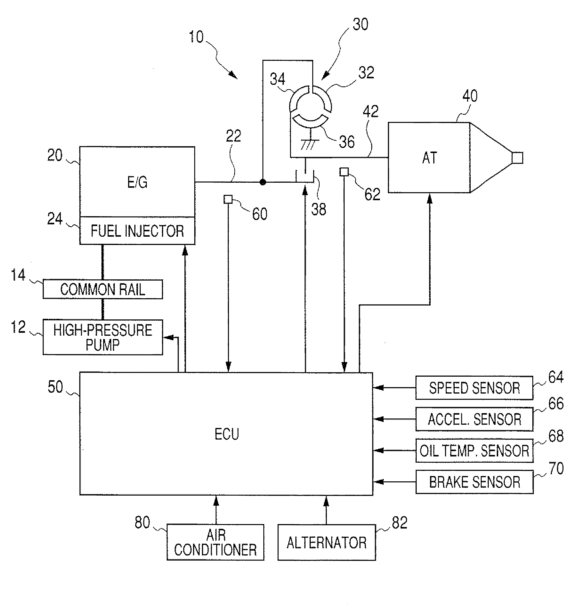
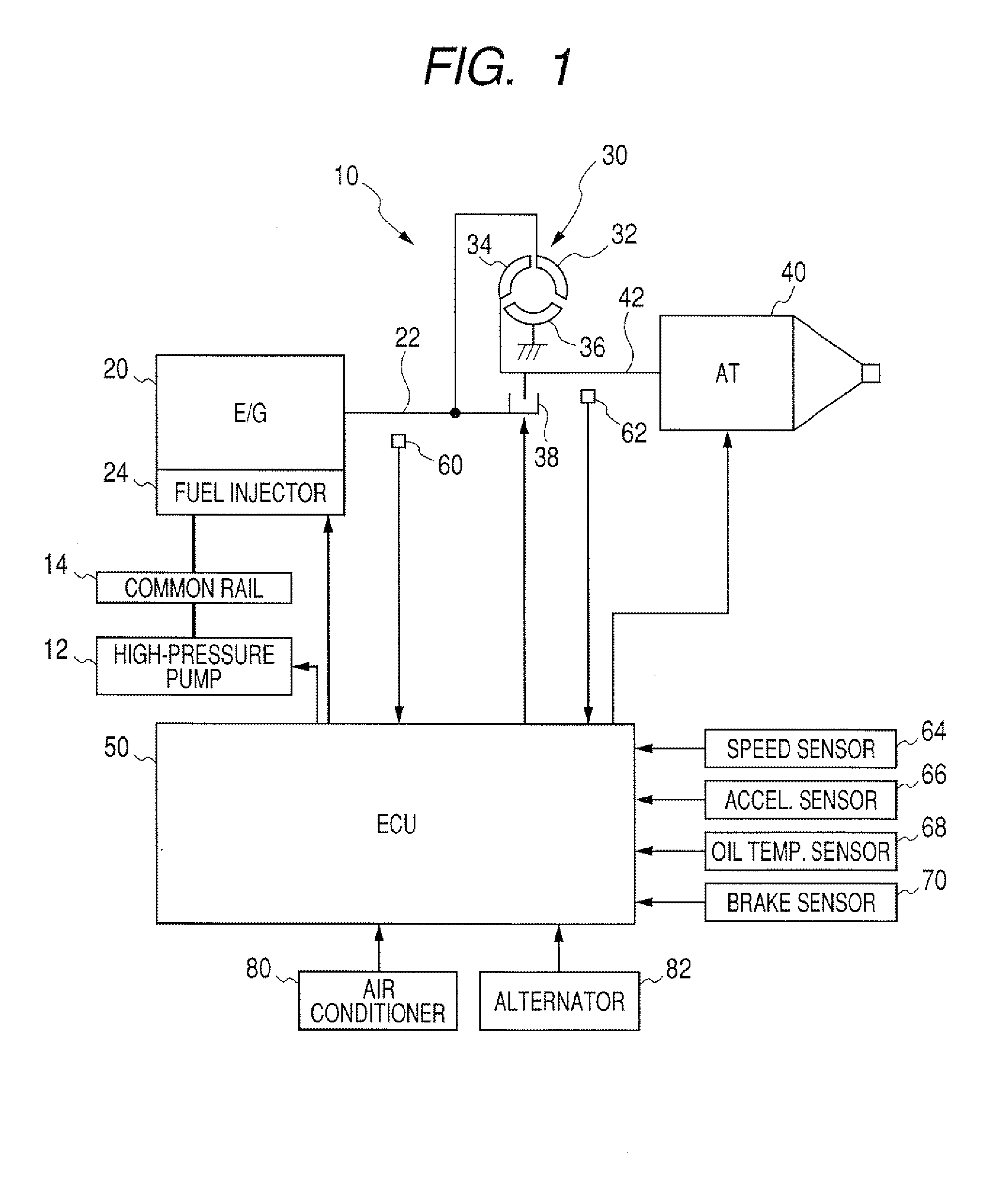
[0031]Referring to the drawings, wherein like reference numbers refer to like parts in several views, particularly to FIG. 1, there is shown an accumulator fuel injection system 10 according to the invention which is engineered, as an example, as a common rail fuel injection system for automotive diesel engines.

[0032]The fuel injection system 10 includes a high-pressure pump 12, a common rail 14, fuel injectors 24, and an electronic control unit (ECU) 50 and works to control the injection of fuel into a diesel engine 20 which is connected to driven wheels of an automotive vehicle through a torque converter 30 and an automatic transmission 40.

[0033]The high-pressure pump 12 is of a typical known structure which has plungers reciprocating following rotation of a cam of a camshaft 22 of the diesel engine 20 to compress the fuel, as sucked into pressure chambers sequentially. The ECU 50 works to control the amount of current applied to a suction control valve (not shown) installed in th...


PUM


Abstract

A fuel injection control apparatus for an internal combustion engine is provided. A controller directs a fuel injector to spray a learning injection quantity of fuel and determines a resulting increase in speed of the engine. The controller determines the quantity of the fuel actually sprayed from the fuel injector based on the increase in speed of the engine and calculates a correction factor which compensates for a difference between the learning injection quantity and the actual injection quantity. The controller also determines a variation in load acting on a driving member of a torque transmission mechanism. When such a variation is great undesirably, the controller stops spraying the learning injection quantity. The controller may determine the increase in speed of the engine based on the degree of the variation in load. This ensures the accuracy in calculating the correction factor regardless of the variation in load.

Description

CROSS REFERENCE TO RELATED DOCUMENT[0001]The present application claims the benefit of Japanese Patent Application No. 2007-193685 filed on Jul. 25, 2007, the disclosure of which is incorporated herein by reference.BACKGROUND OF THE INVENTION[0002]1. Technical Field of the Invention[0003]The present invention relates generally to a fuel injection control apparatus for an internal combustion engine which may be employed in a common rail fuel injection system designed to learn the quantity of fuel injected into the engine to correct or compensate for a difference between a target quantity of fuel to be sprayed from a fuel injector and a quantity of fuel actually sprayed from the fuel injector.[0004]2. Background Art[0005]Fuel injection systems are known which are designed to learn a variation in quantity of fuel sprayed from fuel injectors due to the aging thereof and correct a control signal to be outputted to the fuel injector so as to compensate for such a variation. For example, J...

Claims


Application Information

Patent Timeline
IPC IPC(8): F02D41/30
CPCF02D41/0087F02D41/123F02D41/2467F02D41/2438F02D41/1497
Inventor ASANO, MASAHIROTAKEMOTO, EIJITARUSAWA, YUUKI
Owner DENSO CORP
Features
  • R&D
  • Intellectual Property
  • Life Sciences
  • Materials
  • Tech Scout
  • Unparalleled Data Quality
  • Higher Quality Content
  • 60% Fewer Hallucinations
Learn More