Self calibrating cable for a high definition digital video interface

a digital video interface and self-calibration technology, applied in the field of high-speed cables, can solve the problems of increased risk of misinterpreting the received data at the receiver end of the cable, inability to actually sample the signal, and inability to save the count and delay valu

a digital video interface and self-calibration technology, applied in the field of high-speed cables, can solve the problems of increased risk of misinterpreting the received data at the receiver end of the cable, inability to actually sample the signal, and inability to save the count and delay valu

US20090030635A1Active Publication Date: 2009-01-29REDMERE TECH

Image

  • Self calibrating cable for a high definition digital video interface
  • Self calibrating cable for a high definition digital video interface
  • Self calibrating cable for a high definition digital video interface

Examples


Embodiment Construction

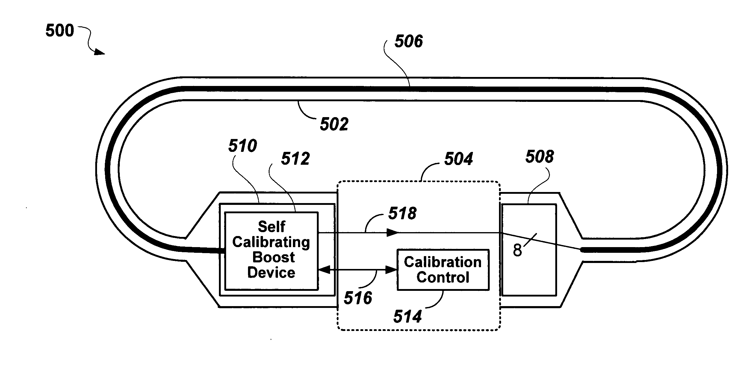
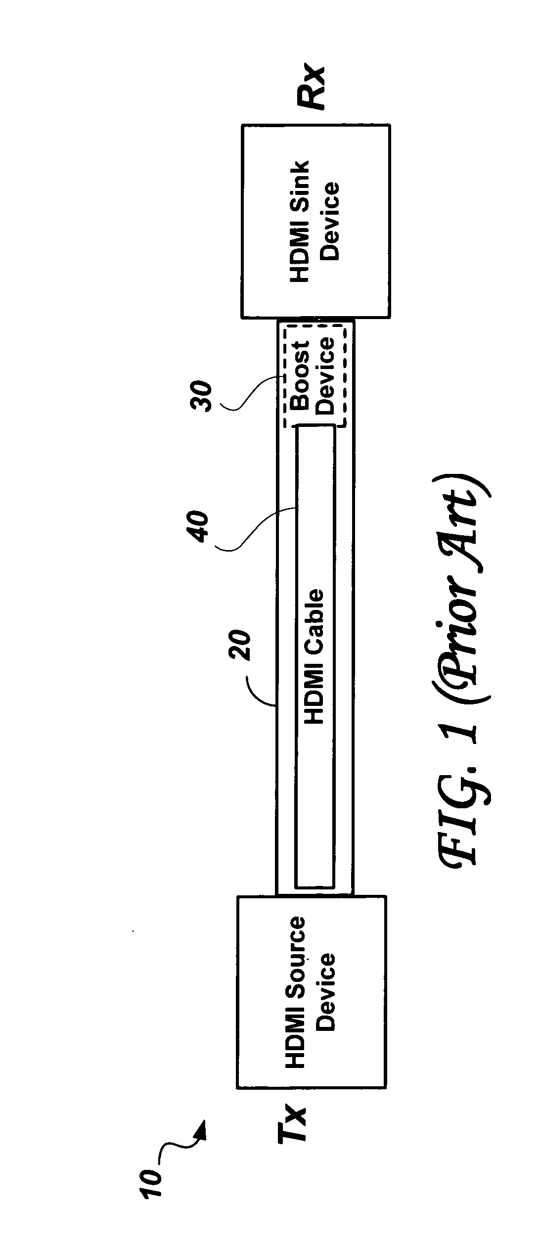
[0133]Briefly summarized, it is an objective of the present invention to modify the boost device such that a method of self calibration is enabled by looping the cable from its output back to its input, while control of the parameter selection is performed by a very simple device attached only to the low speed HDMI control bus. The prior art solution (FIGS. 3 to 6) to calibrating a HDMI cable with an embedded boost device has been presented in some detail in order to gain an appreciation of the simplicity of the present invention in which no external high-speed test equipment is required.

[0134]FIG. 7 shows a self-calibration setup 500 including a self calibrating HDMI cable 502 and a Calibration Fixture 504. The self calibrating HDMI cable 502 includes a basic (passive) cable 506; an input connector 508; and an output connector 510 which includes a self calibrating (SC) Boost Device 512. The Calibration Fixture 504 includes a calibration control 514 which may be realized in a micro ...


PUM


Abstract

An HDMI cable may exhibit frequency dependent signal attenuation, inter symbol interference, and inter-pair skew. A boost device integrated with the cable can compensate for such impairments of the cable. A self calibrating cable with a boost device of the embodiment of the invention is described, in which parameters that control the response of the boost device are set optimally in a self-calibrating process comprising looping the boosted cable on itself through a calibration fixture that contains a calibration control device. The boost device includes pattern generators and a sampling circuit. Each high speed channel of the cable is separately tested and calibrated with the help of one of the other channels serving as a sampling channel.

Description

RELATED APPLICATIONS[0001]The present invention claims benefit from the U.S. provisional application Ser. No. 60 / 935,080 to Horan, John et al. filed on Jul. 25, 2007 entitled “Circuits and Methods for Gigabit Data Recovery and Digital Repeater Implementation”, which is incorporated herein by reference.FIELD OF THE INVENTION[0002]The present invention relates to high speed cables that carry serially encoded differential signals between electronic equipments, and in particular, multi-conductor cables with embedded boost devices for interconnecting audio-visual equipment.BACKGROUND OF THE INVENTION[0003]The distribution of television signals has increasingly become based on digital methods and digitally encoded forms of video and audio signals. At the same time, higher resolution (high definition TV) has become available in the market place, commensurate with larger and higher definition displays. To meet the requirement of interconnecting such high definition displays with digital sig...

Claims


Application Information

Patent Timeline
29 Jan 2009
Publication
US20090030635A1
IPC
G01R35/00
CPC
H04L1/243; H04L1/205
Inventors
HORAN, JOHN MARTIN; KEANE, JOHN ANTHONY