
Printed wiring board structure and electronic apparatus

a wiring board and electronic equipment technology, applied in the direction of cross-talk/noise/interference reduction, sustainable manufacturing/processing, final product manufacturing, etc., can solve the problems of high density mounting of devices on the substrate, sub-substrates miniaturization,

Inactive Publication Date: 2009-02-05
KK TOSHIBA
View PDF1 Cites 13 Cited by
  • Summary
  • Abstract
  • Description
  • Claims
  • Application Information

AI Technical Summary

Benefits of technology

[0005]In an electronic apparatus such as personal computer, a circuit board is received as a main constituent component in a computer housing. The circuit board is mounted with a plurality of semiconductor packages each called a chip set including a CPU and peripheral circuits around the CPU. The circuit board mounted with the semiconductor packages requires high density wiring and high density mounting to achieve high speed signal processing and high performance. Recently, for example, PCI-Express and SATA (Serial-ATA) have been proposed as a technique of achieving the high speed signal processing. Specifically, a high-speed bus interface using a differential signal and a source-synchronous bus interface by source-synchronous transmission are frequently employed. In these interface circuits, a connection interface technique between semiconductor devices capable of achieving the high speed signal transmission is required.

Problems solved by technology

For this reason, there is a problem to achieve substrate miniaturization and high density mounting of the devices on the substrate.
As a result, there is a problem in adaptability to achieve high-speed bus connection between semiconductor devices.

Method used


Image

  • Printed wiring board structure and electronic apparatus
  • Printed wiring board structure and electronic apparatus
  • Printed wiring board structure and electronic apparatus

Examples


first embodiment

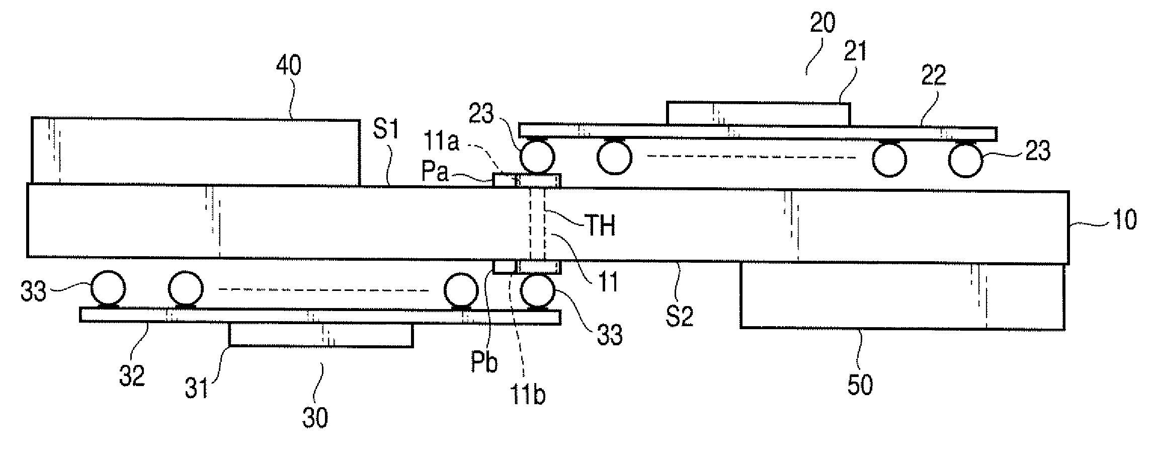
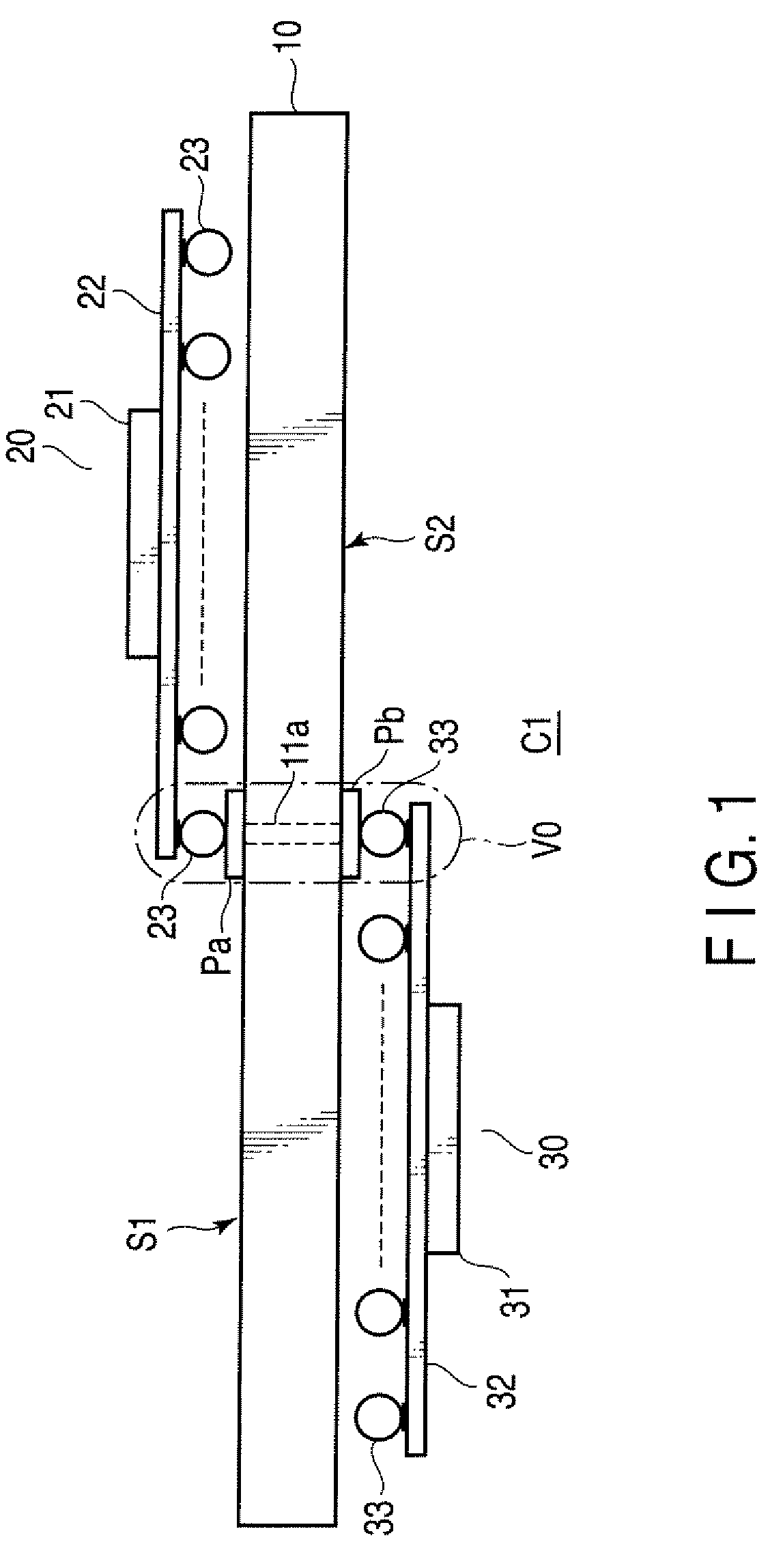
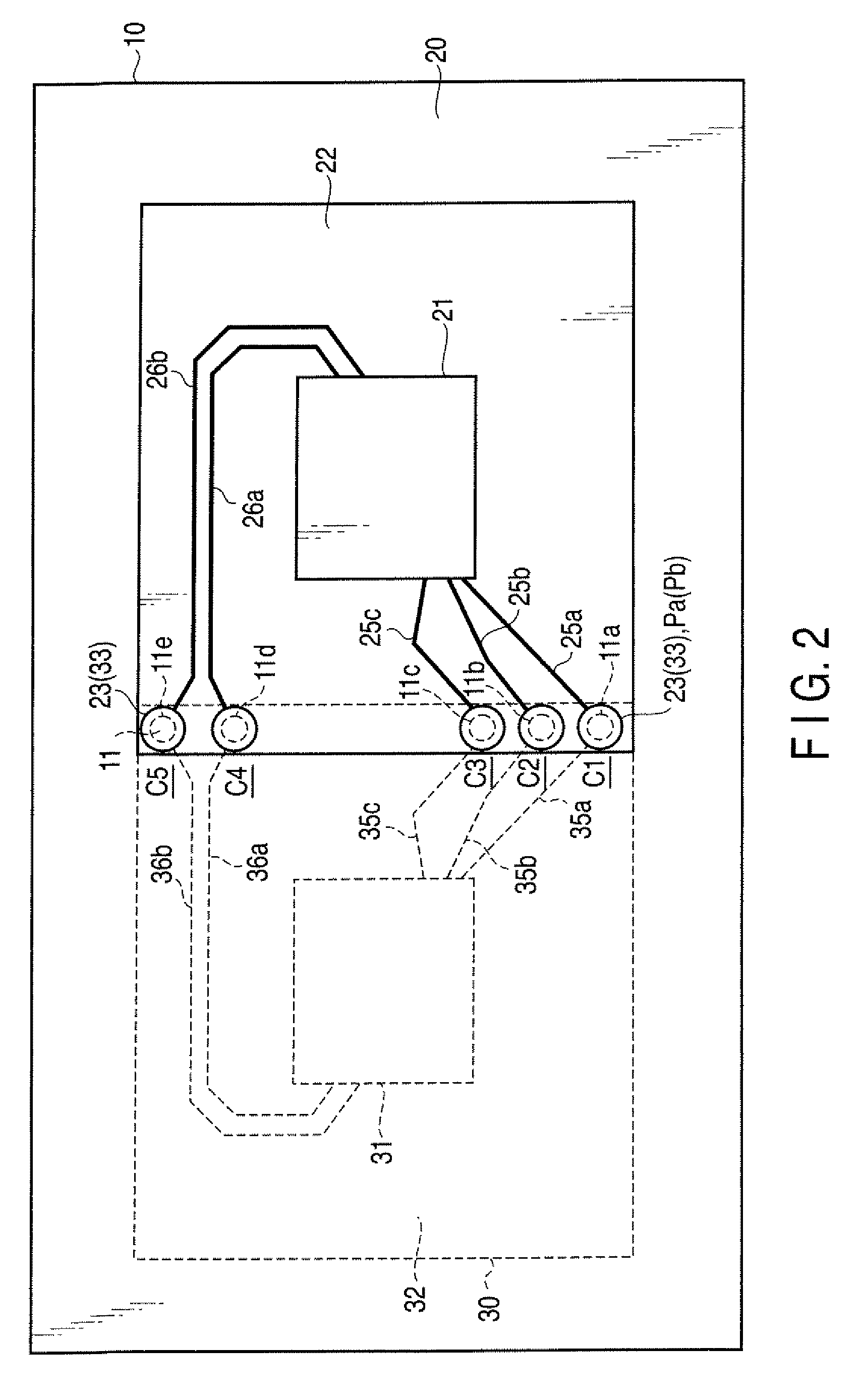
[0021]According to the present invention, the printed wiring board structure mainly includes a multi-layer structure printed wiring board 10, a first semiconductor package (hereinafter, referred to as BAG component) 20 and a second semiconductor package (hereinafter, referred to as BAG component) 30. Specifically, as shown in FIG. 1 and FIG. 2, the printed wiring board 10 has the front and back component mounting surfaces S1, S2. The printed wiring board 10 further has an inter-chip connection part V0 in a selected area thereof. In this case, the part V0 is set at a center part of the board 10. In the inter-chip connection part V0, a plurality of through conductors penetrating between the foregoing component mounting surfaces S1, S2 are arrayed. The first and second semiconductor packages 20 and 30 are mounted on the front and back component mounting surfaces S1, S2 of the printed wiring board 10, respectively so that they are partially overlapped via the foregoing inter-chip connec...

second embodiment

[0044]FIG. 9 relates to the present invention.

[0045]According to the second embodiment, an electronic apparatus is configured using a circuit board having the printed wiring board structure shown in FIG. 8 according to the modification of the first embodiment. FIG. 9 shows an embodiment of the present invention applied with the printed wiring board structure shown in FIG. 8 according to the modification of the first embodiment to a small-sized electronic apparatus such as handy type portable computer.

[0046]As shown in FIG. 9, a main body 2 of a portable computer 1 is attached with a display housing 3, which is freely rotatable via hinge mechanisms h. The main body 2 is provided with a control panel such as a pointing device 4 and a keyboard 5. The display housing 3 is provided with a display device 6 such as an LCD, for example.

[0047]The main body 2 is further provided with a circuit board (mother board) 8 having a built-in control circuit for controlling the foregoing control panel...


PUM


Abstract

According to one embodiment, a printed wiring board structure includes first and second semiconductor packages each including a substrate, and a printed wiring board including first and second component mounting surfaces having a relationship given as front and back surfaces and an inter-chip connection part provided at one portion thereof, the inter-chip connection part being provided with a plurality of arrayed through conductors penetrating through the first and second component mounting surfaces, wherein the substrates of the first and second semiconductor packages are arranged on the printed wiring board in a positional relationship such that the substrates mounted on the component mounting surfaces are partially overlapped via the printed wiring board, the external connection electrodes provided on the substrates are arrayed on the overlapped portion and are conductively connected to the through conductors arrayed in the inter-chip connection part.

Description

CROSS-REFERENCE TO RELATED APPLICATIONS[0001]This application is based upon and claims the benefit of priority from Japanese Patent Application No. 2007-199343, filed Jul. 31, 2007, the entire contents of which are incorporated herein by reference.BACKGROUND[0002]1. Field[0003]One embodiment of the present invention relates to a printed wiring board structure in which a semiconductor package having a semiconductor chip loaded on a substrate is mounted on the front and back surfaces of a printed wiring board.[0004]2. Description of the Related Art[0005]In an electronic apparatus such as personal computer, a circuit board is received as a main constituent component in a computer housing. The circuit board is mounted with a plurality of semiconductor packages each called a chip set including a CPU and peripheral circuits around the CPU. The circuit board mounted with the semiconductor packages requires high density wiring and high density mounting to achieve high speed signal processin...

Claims


Application Information

Patent Timeline
Patent Type & Authority Applications(United States)
IPC IPC(8): H01L23/495
CPCH05K1/0231H05K1/181H05K2201/09481H05K2201/0949H05K2201/096H01L2924/0002H05K2201/10545H05K2201/10734H01L2924/00H05K1/0243Y02P70/50
Inventor KOGA, YUICHI
Owner KK TOSHIBA
Learn More