Method for inspecting a foreign matter on mirror-finished substrate

a technology of mirror-finished substrate and foreign matter, applied in the direction of image enhancement, instruments, image data processing, etc., can solve the problems of a large amount of time and effort required in writing signals over a multiplicity of tracks, a large amount of cost, and the need for many servo writers and maintenance/managing

Inactive Publication Date: 2009-02-05
PANASONIC CORP
View PDF4 Cites 11 Cited by
  • Summary
  • Abstract
  • Description
  • Claims
  • Application Information

AI Technical Summary

Benefits of technology

[0025]The foreign-matter inspection method on mirror-finished substrate can clearly detect an inspection area of a mirror-finished substrate provided as a substrate-under-inspection and positively extract a foreign matter or projection existing on the mirror-finished surface provided as an inspection area thereof thoroughly throughout the entire inspection area. Particularly where there exists a foreign matter close to or in contact with a contour of the inspection area of the substrate-under-inspection, a projection image can be clipped out with clarity. This allows for detecting a foreign matter or projection present on the mirror-finished substrate without using an expensive measuring instrument such as a laser dimension-measuring instrument.
[0026]According to the foreign matter inspection method of the invention, inspection can be conducted throughout the entire inspection area because foreign-matter detection is performed after estimating an inspection area by use of the image data the substrate-under-inspection has been taken an image of at a contour of the inspection area and applying an mask to the image data in a portion other than the inspection area. Furthermore, the image of a foreign matter or projection in proximity to or in contact with the contour of the inspection area can be separated from the image of inspection-region contour. Accordingly, the foreign matter present close to the contour can be positively detected, thus providing a great effect that a foreign matter or projection existing on a magnetic disk surface can be inspected without using such an expensive measuring instrument such as a laser dimension-measuring instrument.

Problems solved by technology

However, the following disadvantages exist in the formatting by means of the foregoing servo writer.
Firstly, much time is required in writing signals over a multiplicity of tracks while accurately positioning the head in position.
Secondly, a great deal of cost is needed in introducing many servo writers and maintaining / managing those.
Such disadvantages are more serious as track density improves and track count increases.
However, the conventional foreign-matter inspection method and apparatus is to correctly measure the outer peripheral edge position of the disk, thus being required to use an expensive measuring instrument, such as a laser dimension measuring instrument.
This raises a disadvantage of increasing apparatus price.
Generally, chamfer is low in working accuracy wherein chamfer dimension has a larger tolerance.
Accordingly, even if the disk outer peripheral edge position is measured correctly, it is not easy to correctly determine a contour of the planar region to be inspected.
Due to this, there is disadvantageously an increasing possibility to erroneously recognize the light irregularly reflected by the chamfer of the disk as light reflected from a foreign matter.

Method used


Image

  • Method for inspecting a foreign matter on mirror-finished substrate
  • Method for inspecting a foreign matter on mirror-finished substrate
  • Method for inspecting a foreign matter on mirror-finished substrate

Examples


embodiment 1

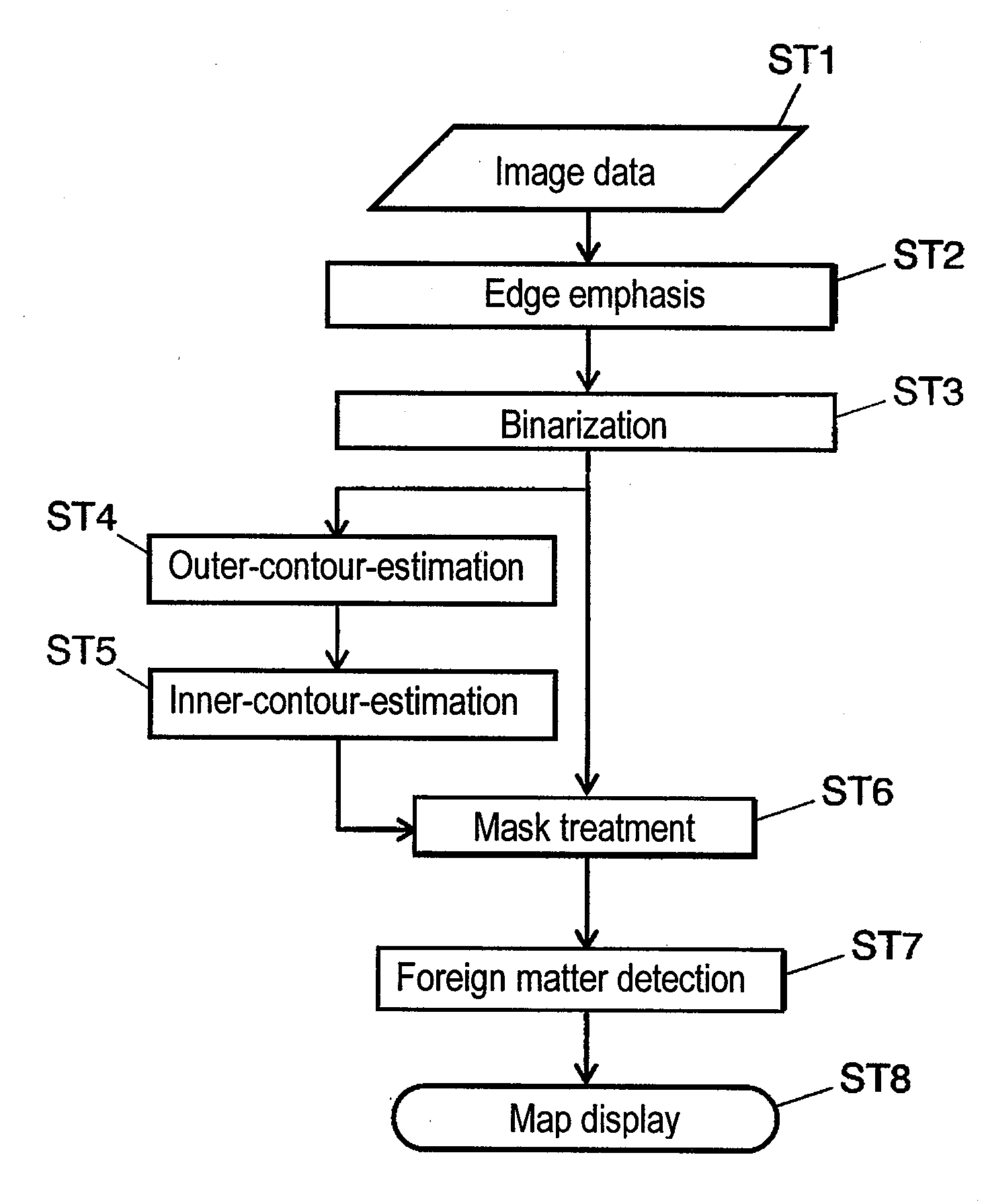
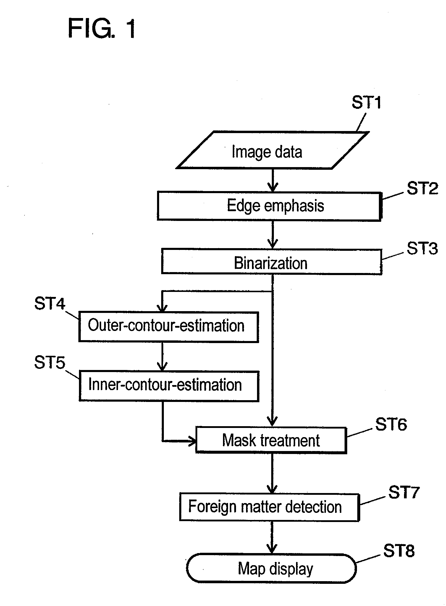
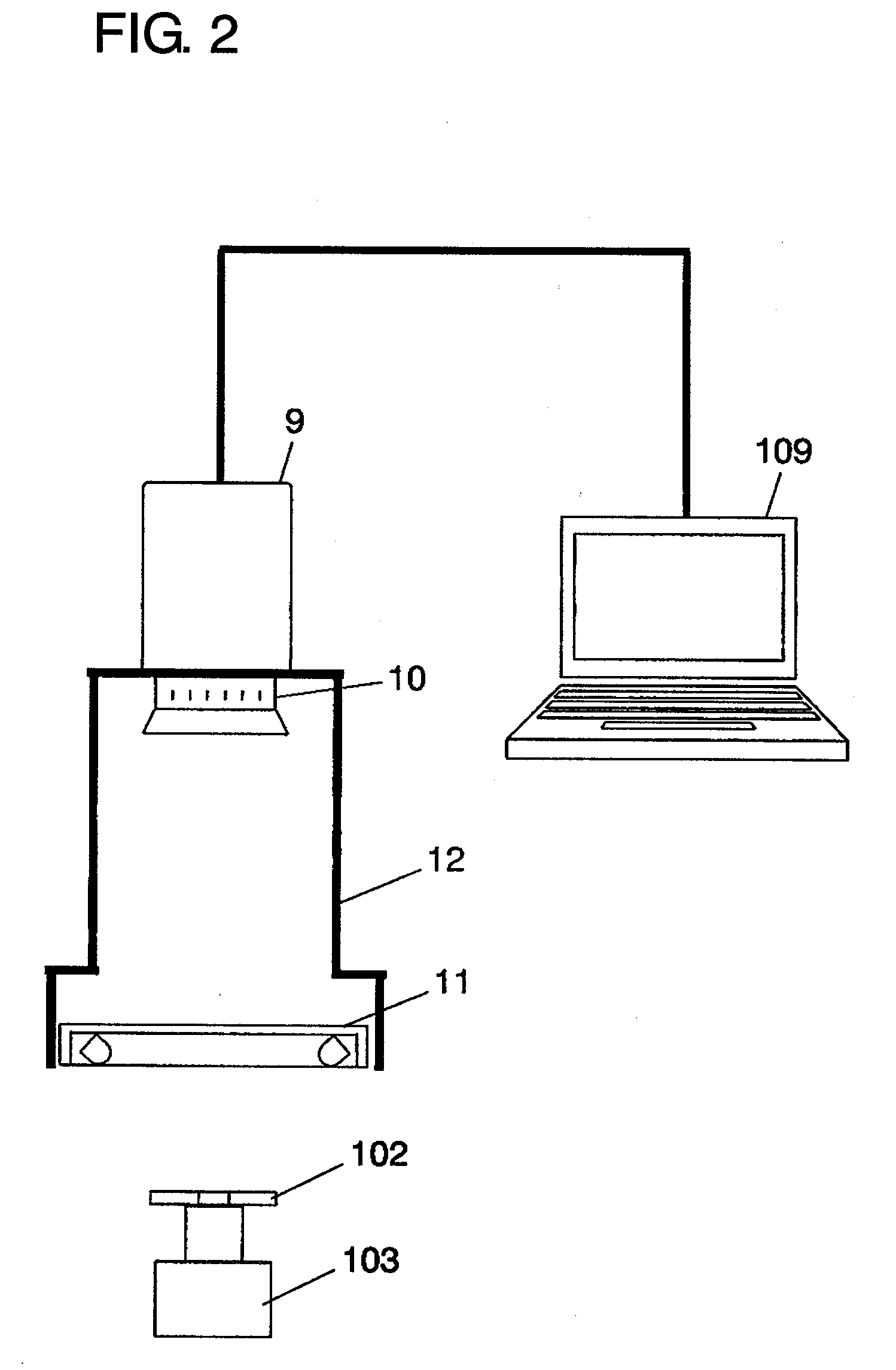
[0075]FIGS. 1 to 11 are figures explaining a foreign matter inspection method on mirror-finished substrate according to embodiment 1 of the present invention. FIG. 1 is a flowchart of the foreign matter inspection method on mirror-finished substrate according to embodiment 1 of the present invention. FIG. 2 is a schematic diagram of an inspection apparatus to be used in step ST1. FIG. 3 is a broken-away perspective view of a magnetic disk, for showing a relationship between illumination light and reflection light. FIG. 4 is a figure showing image data. FIG. 5 is a figure showing the image data emphasized at edges. FIG. 6 is a figure showing the image data processed with binarization. FIG. 7 is a plan view showing how to detect a sampling point at outer periphery. FIG. 8 is a plan view showing how to detect a sampling point at inner periphery. FIG. 9 is a figure showing mask image data. FIG. 10 is a figure showing the mask-treated image data. FIG. 11 is a map figure showing the coord...

embodiment 2

[0118]FIG. 12 is a schematic diagram of an inspection apparatus for explaining a foreign matter inspection method on mirror-finished substrate according to embodiment 2 of the present invention. FIG. 13 is a figure showing the image data obtained by the relevant inspection apparatus.

[0119]In FIG. 12, irregular reflection plate 16 is to irregularly reflect the illumination light of from LED illuminator 11. The inspection apparatus of embodiment 2 differs from embodiment 1 in that magnetic disk 102 is rested on irregular reflection plate 16. The others are identical to the inspection apparatus of embodiment 1, and hence omitted to explain.

[0120]FIG. 13 is a figure showing the image data acquired by the inspection apparatus shown in FIG. 12. Irregular-reflection-plate images Z6, Z7 are captured by introducing the reflection light upon irregular reflection plate 16 to imager device 9. By thus providing irregular reflection plate 16, contours of mirror-finished surface 13 of magnetic dis...


PUM


Abstract

Provided is a foreign matter inspection method for positively detecting a foreign matter in the neighborhood of the edge of a mirror-finished substrate without fail. Edge-emphasis and binarization are performed following the taking of an image of a substrate-under-inspection at a contour of its inspection area, to further detect a plurality of sampling points representative of a contour of the inspection area. An estimated inspection area is determined by determining the size, position and rotation angle of contour lines defined, size-reducibly, from the coordinates of the plurality of sampling points. After applying a mask to the binary image data in an area other than the estimated inspection area, a foreign-matter detection step is performed.

Description

TECHNICAL FIELD[0001]The present invention relates to a foreign matter inspection method that inspects a projection or foreign matter on an object surface by emitting light to an object surface and detecting the reflection light thereof, and more particularly to a foreign matter inspection method on mirror-finished substrate, e.g. a hard disk substrate or a semiconductor silicon wafer.BACKGROUND ART[0002]Recently, the hard disk drive, representative of a magnetic disk device, is in a conspicuous trend toward the increase of recording density in order to realize small size and large capacity, whose track width is reduced down to 1 μm or smaller. In order for the head to correctly scan over such a narrow track, the head-tracking servo technology plays an important role. The presently available hard disk drive, using such track servo art, is to record a tracking servo signal, an address information signal, a reproducing clock signal, etc. at a constant angular interval in one turn of t...

Claims


Application Information

Patent Timeline
Patent Type & Authority Applications(United States)
IPC IPC(8): G06K9/62
CPCG01N21/8851G01N21/94G01N21/95G06T2207/30108G06T7/0006G06T7/0083G06T2207/20164G01N2021/8896G06T7/12
Inventor HAMADA, TAIZOUSUENAGA, TATSUTOSHI
Owner PANASONIC CORP
Why Eureka
Try Eureka