Combination Structure Between Single Cell and Interconnect of Solid Oxide Fuel Cell

a technology of solid oxide fuel cell and interconnection, which is applied in the direction of fuel cell details, fuel cells, electrochemical generators, etc., can solve the problems of long life span, difficult to increase the efficiency of fabrication and operation, and the problems of sealing and mechanical strength are not yet solved, so as to improve the sealing efficiency therebetween and increase the mechanical strength of the fuel cell stack

Inactive Publication Date: 2009-02-05
KOREA ADVANCED INST OF SCI & TECH
View PDF7 Cites 24 Cited by
  • Summary
  • Abstract
  • Description
  • Claims
  • Application Information

AI Technical Summary

Benefits of technology

[0023]According to the present invention, the single cell and the interconnect of the SOFC is combined by excluding the conventional current collector and using the slurry as an adhesive, thereby improving the sealing efficiency therebetween and also considerably increasing the mechanical strength of the fuel cell stack.

Problems solved by technology

Furthermore, it has a long life span due to weak corrosiveness.
However, the problems of sealing and mechanical strength are not yet solved.
That is, the sealing is a difficult work because of the combination of the ceramic components each other and this makes it difficult to increase an efficiency of fabrication and operation, and the mechanical strength is weak and it may be damaged even by thermally dynamic operation or small external shock.
However, the metal-supported SOFC also has a difficulty in the aspects of a scale up issue and a fabricating cost due to a characteristic of the fabricating method thereof.
Particularly, the current collector 40 is disposed between the single cell 2 and the interconnect 50 so as to improve electrical property, but since the current collector 40 has a certain shape, there is a structural limitation in increasing current collecting property and sealing efficiency.

Method used


Image

  • Combination Structure Between Single Cell and Interconnect of Solid Oxide Fuel Cell
  • Combination Structure Between Single Cell and Interconnect of Solid Oxide Fuel Cell
  • Combination Structure Between Single Cell and Interconnect of Solid Oxide Fuel Cell

Examples


Embodiment Construction

[0028]

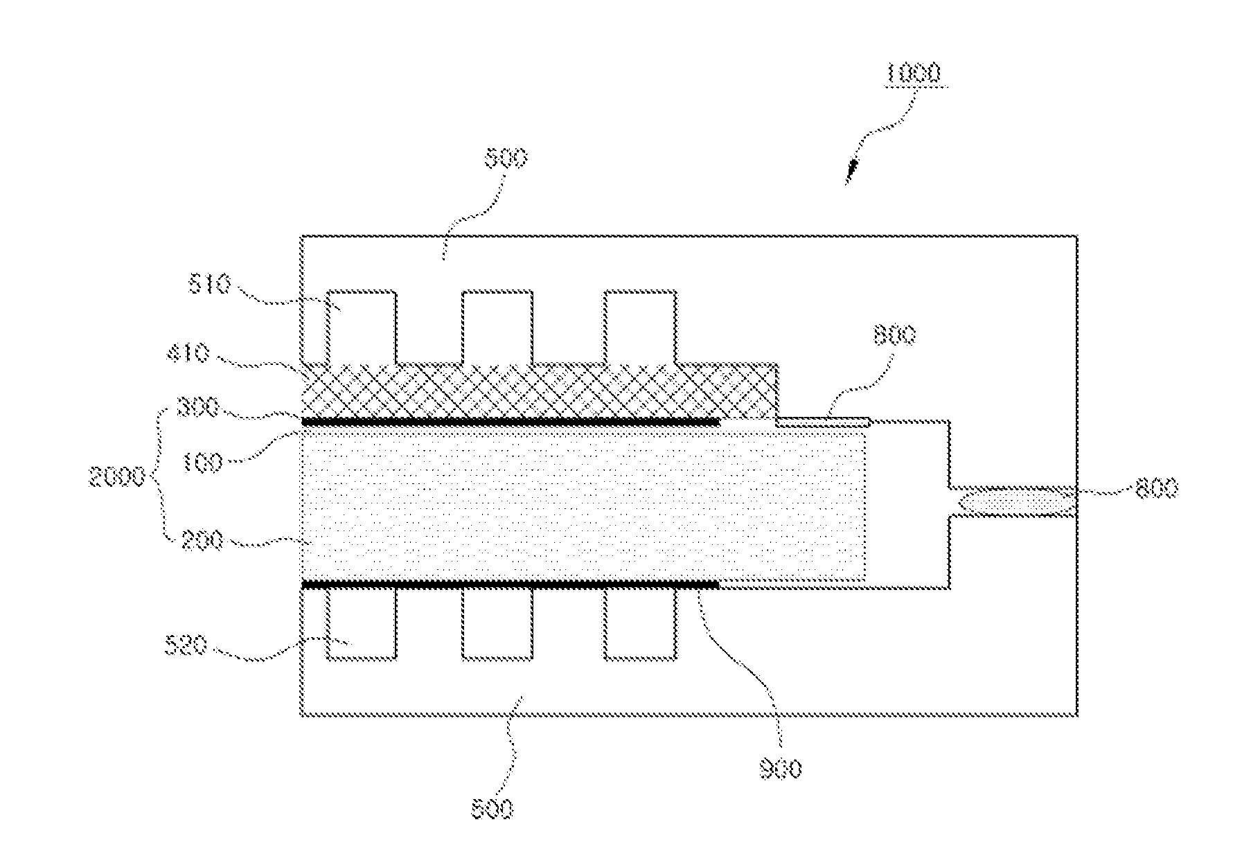
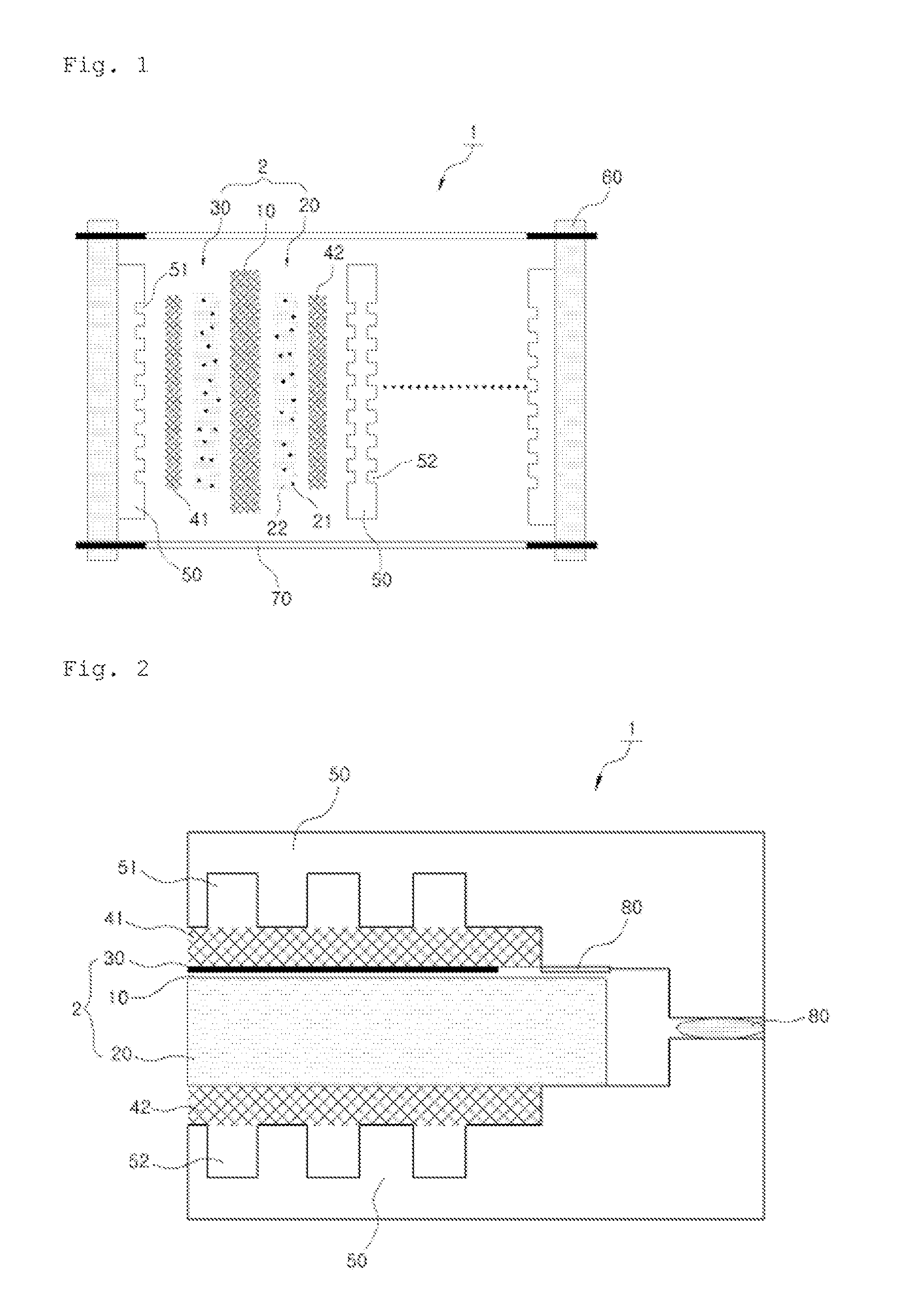
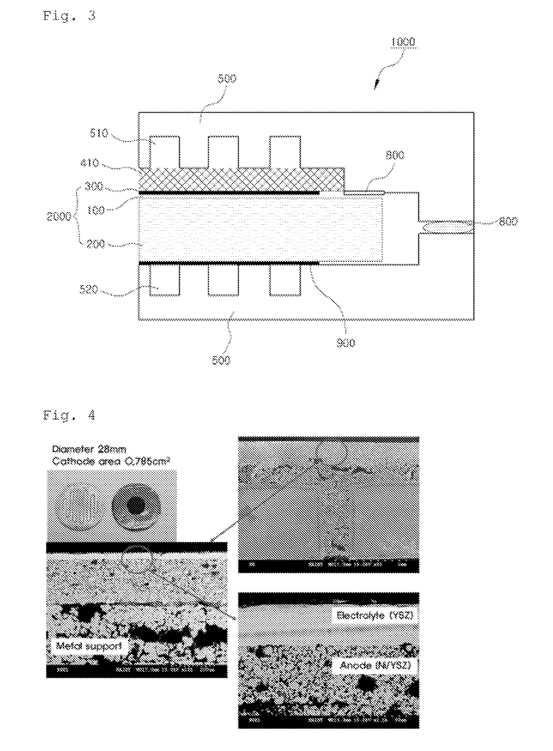
1000:fuel cell2000:unit cell (electrolyte, anode, cathode)100:electrolyte200:anode300:cathode400:current collector410:cathode current collector500:interconnect600:end plate700:coupling member800:sealant900:adhesive

BEST MODE FOR CARRYING OUT THE INVENTION

[0029]Practical and presently preferred embodiments of the present invention are illustrative with reference to the accompanied drawings.

[0030]FIG. 3 is a side sectional view showing a combination structure between a single cell and an interconnect of a SOFC according to the present invention, which is correspondent with FIG. 2 for convenience of explanation.

[0031]However, it will be appreciated that those skilled in the art, on consideration of this disclosure, may make modifications and improvements within the spirit and scope of the present invention.

[0032]According to a combination structure between a single cell 2000 and an interconnect 500 of a solid oxide fuel cell (SOFC) 1000 of the present invention, the SOFC 100 inclu...


PUM

PropertyMeasurementUnit
temperatureaaaaaaaaaa
electrically conductive propertyaaaaaaaaaa
metallic propertyaaaaaaaaaa

Abstract

The present invention relates to a combination structure of a solid oxide fuel cell between an electrode and an interconnect in which the electrode and interconnect are sinter-joined to each other by using slurry in a status that a conventional current collector is excluded, thereby improving a strength and a sealing efficiency. The combination structure between a single cell and an interconnect of a solid oxide fuel cell which comprises electrolyte, and an anode and a cathode which are respectively contacted with both sides of the electrolyte; and an interconnect which are formed at both sides of the single cell and has a cathode passage for supplying air to the cathode and an anode passage for supplying fuel to the anode, is characterized by that one or both sides of the single cell are directly combined with the interconnect.

Description

TECHNICAL FIELD[0001]The present invention relates to a combination structure between a single cell and an interconnect of solid oxide fuel cell, and more particularly, to a combination structure between a single cell and an interconnect of solid oxide fuel cell in which the electrode and interconnect are sinter-joined to each other by using slurry in a status that a conventional current collector is excluded, thereby improving a strength and a sealing efficiency.BACKGROUND ART[0002]A fuel cell, which directly converts chemical energy into electrical energy, is a new green futuristic energy technology which can generates the electrical energy from materials such as oxygen, hydrogen and the like which is found in abundance on the earth.[0003]In the fuel cell, oxygen is supplied to a cathode and hydrogen is supplied to an anode so that an electrochemical reaction is performed in a reverse way of water electrolysis so as to generate electricity, heat and water, thereby producing the el...

Claims


Application Information

Patent Timeline
Patent Type & Authority Applications(United States)
IPC IPC(8): H01M8/10
CPCH01M8/0206H01M8/0236H01M8/0297Y02E60/525H01M2008/1293Y02E60/50H01M8/2425H01M8/02H01M8/24H01M8/0271H01M8/2465
Inventor BAE, JOONGMYEONLEE, CHANGBO
Owner KOREA ADVANCED INST OF SCI & TECH
Why Eureka
Try Eureka