Control system for agricultural working vehicles

Inactive Publication Date: 2009-02-05
CLAAS AGROSYST
View PDF5 Cites 37 Cited by
  • Summary
  • Abstract
  • Description
  • Claims
  • Application Information

AI Technical Summary

Benefits of technology

[0007]The object of this invention is to develop a control system for agricultural working vehicles with at least two sensor systems which generate sensor signals which are vehicle-dependent or dependent on crop characteristics or de

Problems solved by technology

However, the disadvantage of GPS-based devices for position determination, is that signal falsifications caused in particular by run-time errors of the GPS signal or reception interference may result in substantial interferences in the automatic steering of the vehicle.
Under certain circumstances this may lead to a situation where the working vehicle is steered out of the track that is actually to be worked, so that the work quality of the vehicle is substantially impaired.
The particular disadvantage of such a system is that it is always coupled to the position data of two travel route detection systems.
The poorer the quality of the position signals received from the individual travel route detection systems, the greater this deviation will be.
Moreover, such an interaction of a plurality of travel route detection systems does not allow for the fact that in the presence of stamped optical reference lines in the territory to be worked, travel route detect

Method used


Image

  • Control system for agricultural working vehicles
  • Control system for agricultural working vehicles
  • Control system for agricultural working vehicles

Examples


Example

[0039]FIG. 2: shows a flow chart to illustrate the sensor fusion according to the invention.

DESCRIPTION OF THE PREFERRED EMBODIMENTS

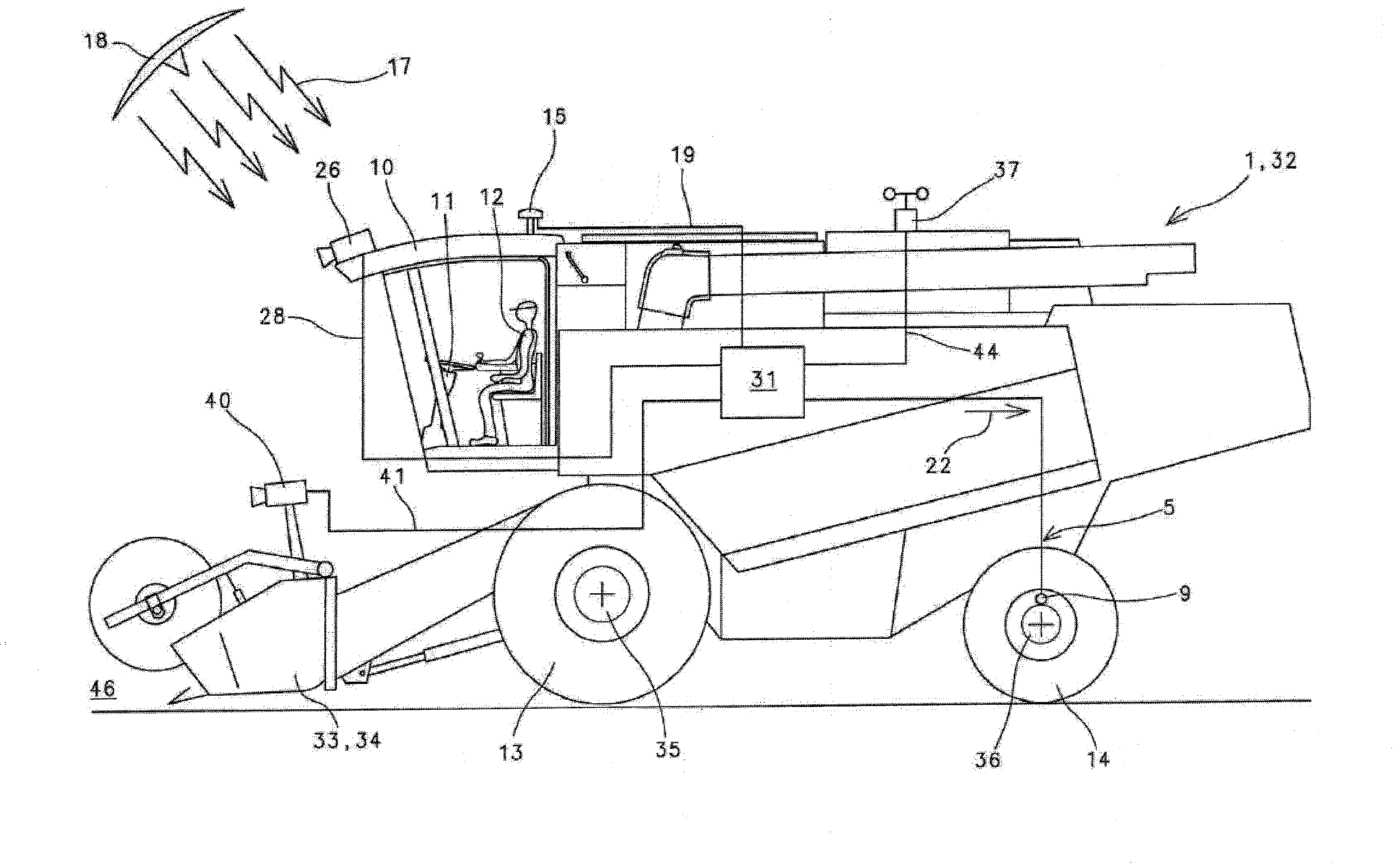
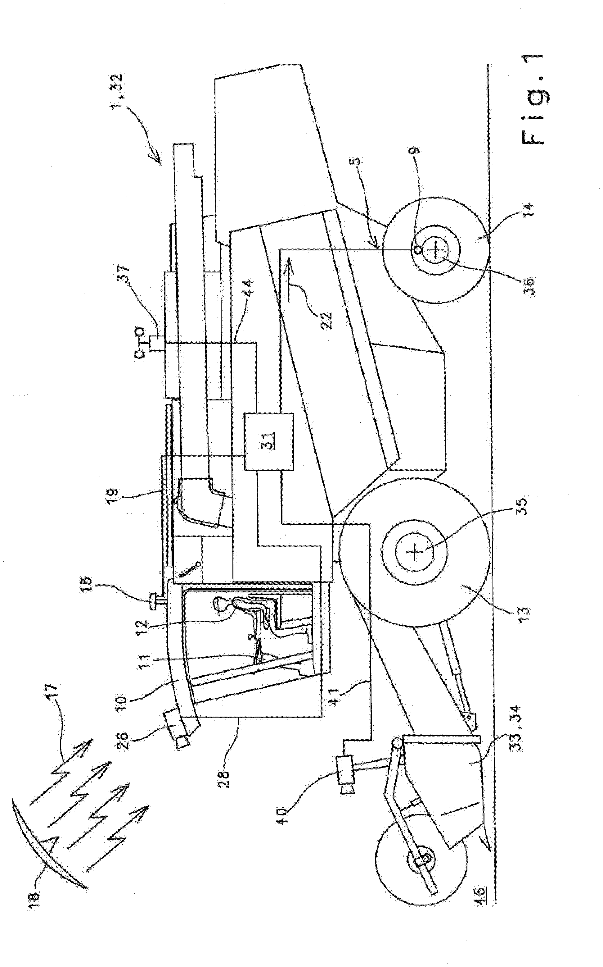
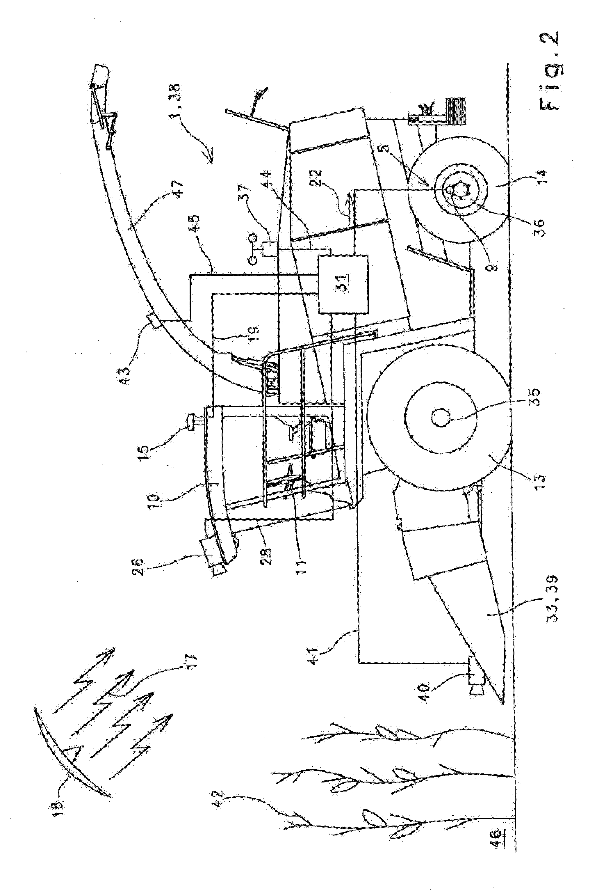
[0040]FIG. 1 shows, by way of example, an agricultural working vehicle 1 constructed as a combine harvester 32, which vehicle has in its front region an front attachment 33 designed as a corn cutter 34. It lies within the scope of the invention for front attachment 33 to be constructed in any manner. It is pointed out here that front attachment 33 may be designed, for example, as a maize header or pick-up. Combine harvester 32 of prior art is provided with a drive axle 35 fitted with wheels 13 and a steering axle 36, which is actively connected in a known manner to a steering cylinder 9 of a steering circuit 5. Operator 12 of combine harvester 32 can control the pressure loading of steering cylinder 9 by conventional means, using steering wheel 11 arranged in vehicle cab 10, and hence effect a steering of combine harvester 32.

[0041]Combine harvester 32 ...


PUM


Abstract

The invention relates to a control system for agricultural working vehicles with at least two sensor systems which generate sensor signals (A, B), wherein the sensor signals (A, B) are vehicle-dependent or dependent on the crop characteristics or a combination of both.
The object of this invention is to develop a control system for agricultural working vehicles in such a manner that a suitable fusion of the sensor signals (A, B) of the sensor systems is achieved, in particular.
This object is achieved according to the invention in that at least one first and at least one second sensor signal processing algorithm (I,II,III,IV,V) is provided in the control system, and in that a selection is made as to which sensor signal processing algorithm (I,II,III,IV,V) is to be used as a function of at least one characteristic parameter (P).

Description

CROSS-REFERENCE TO A RELATED APPLICATION[0001]The invention described and claimed hereinbelow is also described in European Patent Application EP 07015318.4 filed on Aug. 3, 2007. This European Patent Application, subject matter of which is incorporated herein by reference, provides the basis for a claim of priority of invention under 35 U.S.C. 119(a)-(d).BACKGROUND OF THE INVENTION[0002]Control systems for agricultural working vehicles are used, for example, to control so-called tracking systems. The use of tracking systems for fully or partially automatic guide systems of agricultural working vehicles on characteristic virtual or real lines is of considerable, practical importance because the vehicle operator is largely relieved of steering processes that sometimes require great skill. Mechanical tracking systems which generally scan characteristic lines in the territory to be worked by means of mechanical sensors and generate from the detected contours guide signals which guide t...

Claims


Application Information

Patent Timeline
IPC IPC(8): G06F19/00G01C21/20
CPCA01B69/001A01B69/008G05D2201/0201G05D1/0272G05D1/0278G05D1/0246
Inventor HUSTER, JOCHENMOELLER, JENSDIEKHANS, NORBERTAUTERMANN, LUDGERNIENABER, GERHARDHIERONYMUS, PETERWILKEN, ANDREASPEIN, CHRISTOPHMEYER ZU HELLIGEN, LARS-PETERMADSEN, TOMMYKIRK, KRISTIANBLAS, RUFUS
Owner CLAAS AGROSYST
Why Eureka
Try Eureka