Method of producing elliptically polarizing plate and image display apparatus using the elliptically polarizing plate

a technology of elliptically polarizing plates and image display apparatuses, applied in the direction of polarizing elements, instruments, non-linear optics, etc., can solve the problems of film quality variation, high cost and long time, and cannot exhibit desired optical characteristics (such as functions of /4 plates) over a wide wavelength range, so as to achieve no waste, high production efficiency, and low cost

Inactive Publication Date: 2009-02-12
NITTO DENKO CORP
View PDF2 Cites 19 Cited by
  • Summary
  • Abstract
  • Description
  • Claims
  • Application Information

AI Technical Summary

Benefits of technology

[0019]As described above, according to the present invention, the slow axis of the first birefringent layer can be set in an arbitrary direction in the alignment treatment for the substrate, and thus a continuous polarizing film (polarizer) stretched in a longitudinal direction (that is, a film having an absorption axis in a longitudinal direction) can be used. In other words, a continuous first birefringent layer formed on the substrate which is subjected to the alignment treatment to be at a predetermined angle with respect to its longitudinal direction, a continuous transparent protective film, and a continuous polarizing film (polarizer) may be continuously attached together with the respective longitudinal directions in the same direction (by so-called roll to roll). Thus, an elliptically polarizing plate can be obtained at very high production efficiency. According to the method of the present invention, the film need not be cut out obliquely with respect to its longitudinal direction (stretching direction) for lamination. As a result, angles of optical axes do not vary by cut-out film, resulting in an elliptically polarizing film without variation in quality by product. Further, no wastes are produced by cutting of the film, and the elliptically polarizing plate can be obtained at low cost and production of a large polarizing plate is facilitated. Meanwhile, a substrate is peeled off from a laminate having a polarizer, a transparent protective film, a first birefringent layer, and the substrate in the stated order. A polymer film stretched in a width direction and having a slow axis in the width direction is used as the polymer film forming the second birefringent layer. Thus, long sides of the laminate from which the substrate is peeled off and the polymer film may be continuously attached together, and an elliptically polarizing plate can be obtained at very high production efficiency. Further, such the production method is employed to thereby provide an elliptically polarizing plate having excellent adhesiveness between films (layers). The thus-obtained elliptically polarizing plate is optimized to have angles α and β in a relationship represented by an expression 2α+40°<β<2α+50° (wherein, α represents an angle between an absorption axis of the polarizer and the slow axis of the first birefringent layer (λ / 2 plate), and β represents an angle between the absorption axis of the polarizer and the slow axis of the second birefringent layer (λ / 4 plate)), to thereby provide an image display apparatus with broadband and wide viewing angle. The relationship is comprehensive, and requires no studies on lamination direction depending on products by trial and error. That is, the relationship may be used for almost all combinations of the polarizer, λ / 2 plate, and λ / 4 plate, to thereby realize excellent circular polarization characteristics. As a result, optimization of the circular polarization characteristics can be extremely generalized and facilitated.

Problems solved by technology

Thus, the λ / 4 plate has a problem in that it cannot exhibit desired optical characteristics (such as functions of the λ / 4 plate) over a wide wavelength range.
However, such a film has problems in cost.
The variation may result in problems of variation in quality by product and production requiring high cost and long time.
Further problems include increased waste by cutting out of the films, and difficulties in production of large films.
However, the method has a problem in that the adjustment involves difficulties.
Further, at present, an angle between an absorption axis of a polarizing film and a slow axis of each retardation plate is adjusted by product, and comprehensive means for optimization of the angle has not been found yet.

Method used


Image

  • Method of producing elliptically polarizing plate and image display apparatus using the elliptically polarizing plate
  • Method of producing elliptically polarizing plate and image display apparatus using the elliptically polarizing plate
  • Method of producing elliptically polarizing plate and image display apparatus using the elliptically polarizing plate

Examples


example 1

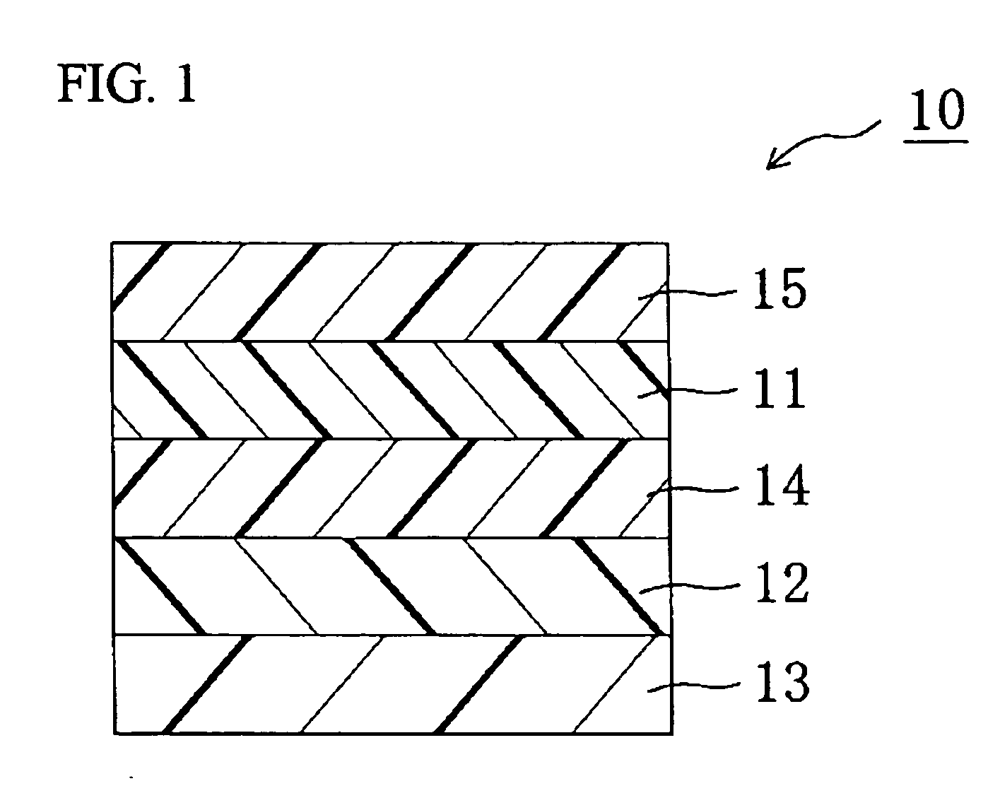
I. Preparation of Elliptically Polarizing Plate as Shown in FIG. 1

[0132]I-a. Alignment Treatment for Substrate (Preparation of Aligned substrate)

[0133]Substates were subjected to alignment treatment, to thereby prepare aligned substrates.

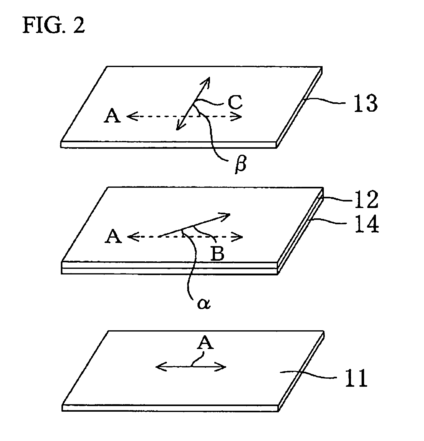
[0134]Substrates (1) to (6): A surface of a polyethylene terephthalate (PET) film (thickness of 50 μm) was subjected to rubbing at a rubbing angle shown in Table 1 below by using a rubbing cloth, to thereby form each of aligned substrates.

TABLE 1SubstrateRubbing angle (angle α)(1)13°(2)−13°(3)23°(4)−23°(5)33°(6)−33°

I-b. Preparation of First Birefringent Layer (First Birefringent Layer Formed on Substrate)

[0135]10 g of polymerizable liquid crystal (Paliocolor LC242, trade name; manufactured by BASF Aktiengesellschaft) exhibiting a nematic liquid crystal phase, and 3 g of a photopolymerization initiator (IRGACURE 907, trade name; manufactured by Ciba Specialty Chemicals) for the polymerizable liquid crystal compound were dissolved in 40 g of toluene, ...

example 2

[0144]The elliptically polarizing plates A01 were superimposed to measure a contrast ratio. Table 1 reveals that the elliptically polarizing plate had a relationship represented by an expression β=2α+44°. The elliptically polarizing plate had the minimum angle of 40° and maximum angle of 50° for contrast 10 in all directions, and a difference between the maximum and minimum angles of 10°. The minimum angle of 40° for contrast 10 in all directions was at a preferred level in practical use. Further, the difference between the maximum and minimum angles of 10° was so small that the elliptically polarizing plate had balanced visual characteristics, and thus the difference was also at a verypreferred level inpractical use.

example 3

[0145]The elliptically polarizing plates A21 were superimposed to measure a contrast ratio. Table 1 reveals that the elliptically polarizing plate had a relationship represented by an expression β=2α+49°. The elliptically polarizing plate had the minimum angle of 40° and maximum angle of 60° for contrast 10 in all directions, and a difference between the maximum and minimum angles of 20°. The minimum angle of 40° for contrast 10 in all directions was at a preferred level in practical use.


PUM

PropertyMeasurementUnit
transparentaaaaaaaaaa
birefringentaaaaaaaaaa
temperatureaaaaaaaaaa

Abstract

To provide a method of producing a broadband and wide viewing angle elliptically polarizing plate having excellent properties in an oblique direction, the elliptically polarizing plate, and an image display apparatus.The method of producing an elliptically polarizing plate of the present invention includes the steps of: forming a first birefringent layer on a surface of a transparent protective film; laminating a polarizer on a surface of the transparent protective film; and forming a second birefringent layer on a surface of the first birefringent layer, in which: the first birefringent layer and the polarizer are arranged on opposite sides of the transparent protective film; the step of forming a first birefringent layer includes the steps of: applying a liquid crystal material to an alignment substrate; forming a first birefringent layer on the substrate from the liquid crystal material; and transferring the first birefringent layer to a surface of the transparent protective film; and angles α and β satisfy a predetermined relationship (where, α represents an angle formed between a slow axis of the polarizer and a slow axis of the first birefringent layer, and β represents an angle formed between the absorption axis of the polarizer and a slow axis of the second birefringent layer).

Description

TECHNICAL FIELD[0001]The present invention relates to an elliptically polarizing plate, and to an image display apparatus using the same. The present invention more specifically relates to a method of producing a broadband and wide viewing angle elliptically polarizing plate having excellent characteristics in an oblique direction as well at very high production efficiency, to an elliptically polarizing plate obtained through the method, and to an image display apparatus using the elliptically polarizing plate.BACKGROUND ART[0002]Various optical films each having a polarizing film and a retardation plate in combination are generally used for various image display apparatuses such as a liquid crystal display apparatus and an electroluminescence (EL) display, to thereby obtain optical compensation.[0003]In general, a circularly polarizing plate which is one type of optical films can be produced by combining a polarizing film and a λ / 4 plate. However, the λ / 4 plate has characteristics ...

Claims


Application Information

Patent Timeline
Patent Type & Authority Applications(United States)
IPC IPC(8): G02F1/13363B29D11/00
CPCG02F2001/133638G02B5/3016G02F1/133638G02B5/30
Inventor KAWAMOTO, IKUOUMEMOTO, SEIJIKAMIJOU, TAKASHIYONEZAWA, HIDEYUKIHADA, KAZUYA
Owner NITTO DENKO CORP
Why Eureka
Try Eureka