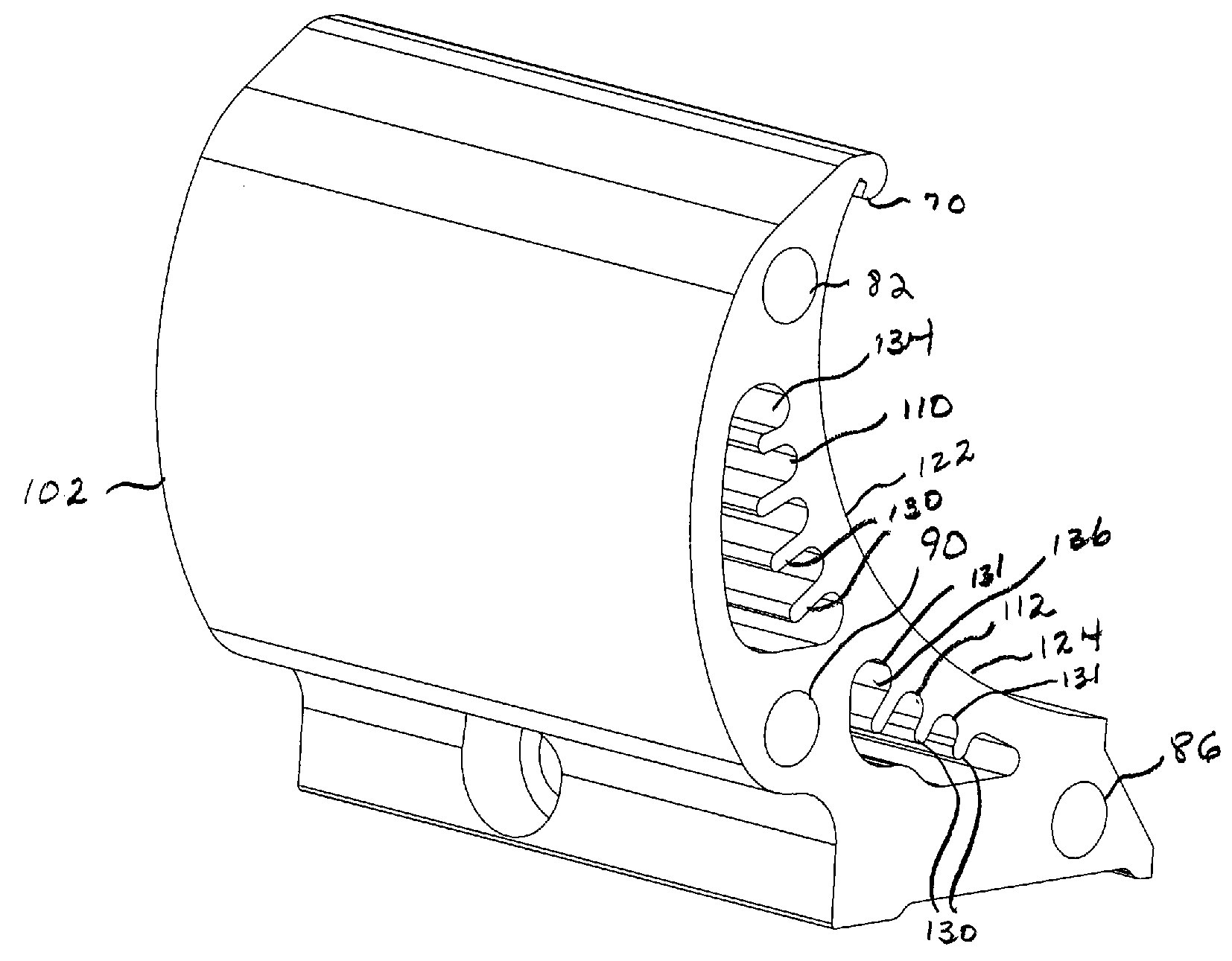
UV module shutter extrusion with internal cooling fins
a technology of shutter extrusion and cooling fin, which is applied in the field of shutters, can solve the problems of generating considerable heat in the lamp used to generate light for this purpose, damage to the substrate, damage to other non-moving components of the printing press, etc., and achieves the effects of improving the heat transfer capability of the shutter extrusion, reducing the risk of damage, and reducing the cost of the press
- Summary
- Abstract
- Description
- Claims
- Application Information
AI Technical Summary
Benefits of technology
Problems solved by technology
Method used
Image

Examples
Embodiment Construction
[0024]Any references to such relative terms as right and left or the like are intended for convenience of description and are not intended to limit the present invention or its components to any one positional or spatial orientation. Each of the features and methods disclosed herein may be utilized separately or in conjunction with other features and methods to provide improved devices of this invention and methods for making and using the same. Representative examples of the teachings of the present invention, which examples utilize many of these features and methods in conjunction, will now be described in detail with reference to the drawings. This detailed description is merely intended to teach a person of skill in the art further details for practicing preferred aspects of the present teachings and is not intended to limit the scope of the invention. Therefore, combinations of features and methods disclosed in the following detailed description may not be necessary to practice...
PUM
| Property | Measurement | Unit |
|---|---|---|
| voltage | aaaaa | aaaaa |
| temperatures | aaaaa | aaaaa |
| temperatures | aaaaa | aaaaa |
Abstract
Description
Claims
Application Information