
Image processing system and method for silhouette rendering and display of images during interventional procedures

a silhouette rendering and image technology, applied in the field of optical data storage and microscopy, can solve the problems of low refresh rate for capturing an entire image, inability to easily and efficiently use optical storage solutions, and unknown applications using optical storage solutions are not robust to shocks, etc., to achieve the effect of significantly increasing the scanning speed

Inactive Publication Date: 2009-02-19
KONINKLIJKE PHILIPS ELECTRONICS NV
View PDF9 Cites 27 Cited by
  • Summary
  • Abstract
  • Description
  • Claims
  • Application Information

AI Technical Summary

Benefits of technology

[0061]It is therefore an object of the invention to provide a system and method for positioning an information carrier in an information carrier scanning system, wherein the scanning speed is significantly increased.
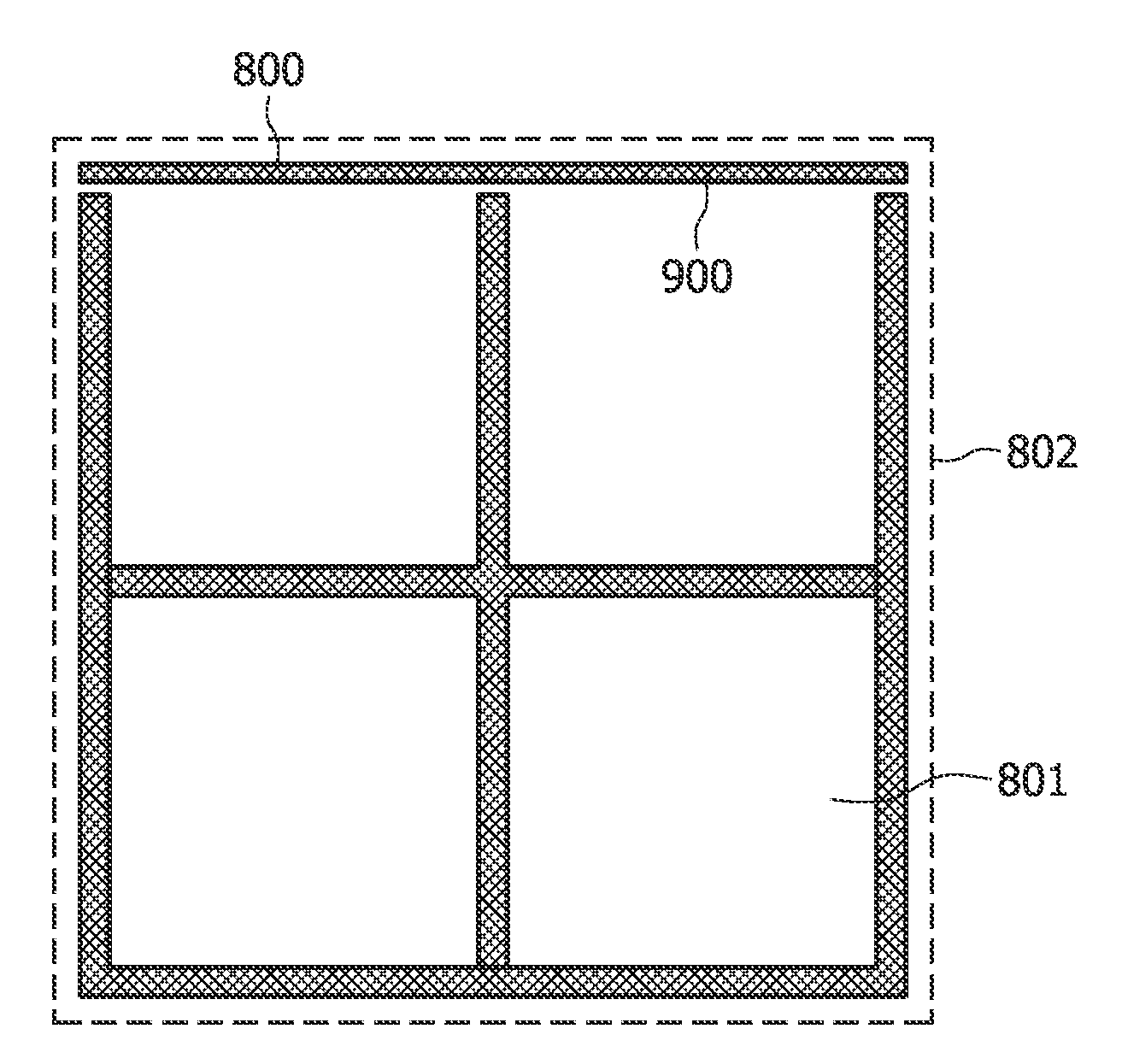
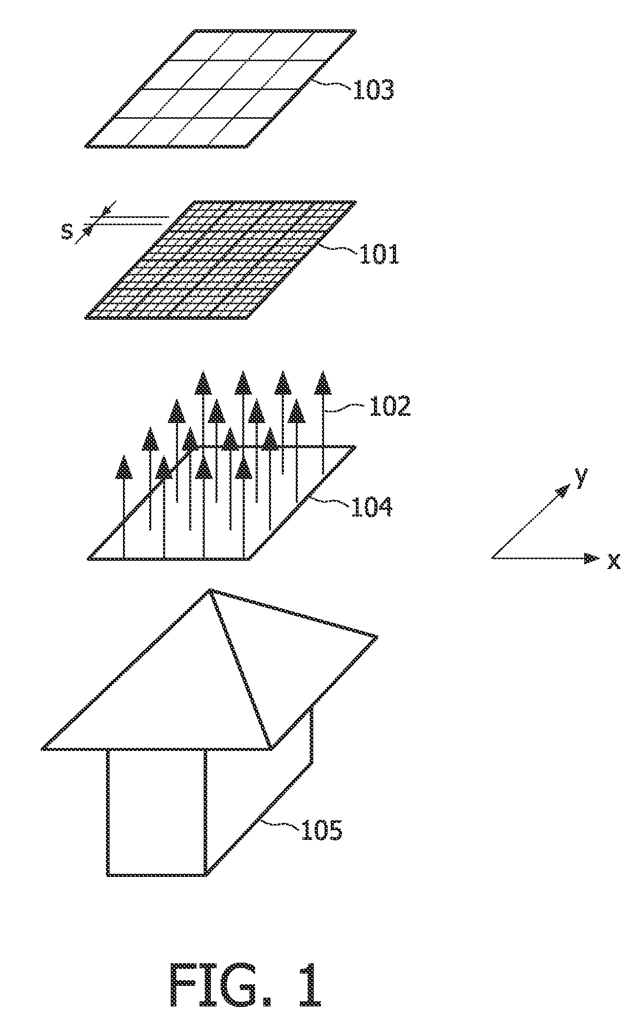
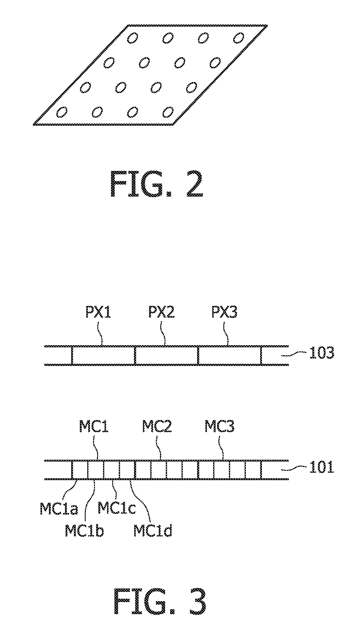
[0062]In accordance with the present invention, there is provided a positioning system for positioning an information carrier in an information carrier scanning apparatus, said information carrier having one or more reference structures, said information carrier scanning apparatus comprising a probe array generating means for generating a probe array comprising an array of light spots, means for applying said probe array to said information carrier so as to generate output light beams, and a sensor for receiving said output light beams, said positioning system comprising means for selecting a region of interest of said information carrier comprising a portion thereof corresponding to said one or more reference structures, narrowing the field of view of said sensor to cover only said region of interest and receiving output light beams in respect thereof and generating respective control signals and means for positioning said information carrier relative to said probe array using said control signals.
[0063]Also in accordance with the present invention, there is provided a method of positioning an information carrier in an information carrier scanning apparatus, said information carrier having one or more reference structures, and said information carrier scanning apparatus comprising a probe array generating means for generating a probe array comprising an array of light spots, means for applying said probe array to said information carrier so as to generate output light beams, and a sensor for receiving said output light beams, the method comprising selecting a region of interest of said information carrier comprising a portion thereof corresponding to said one or more reference structures, narrowing the field of view of said sensor to cover only said region of interest, receiving output light beams in respect of said region of interest and generating respective control signals, and positioning said information carrier relative to said probe array using said control signals.
[0065]Thus, the present invention makes use of the so-called “windowing” option offered in, for example, known CMOS image sensors for increasing the scanning speed in an information carrier scanning system. This enables the speed of detection of information on the information carrier to be increased, while at the same time increasing the update rate of servo position information. Hence the servo bandwidth is increased and more rapid positioning of the scanning spots is facilitated which, in turn, results in an increased information throughput of the system.

Problems solved by technology

However, due to the large amount of moving elements in the drives, known applications using optical storage solutions are not robust to shocks when performing read / write operations, considering the required stability of said moving elements during such operations.
As a consequence, optical storage solutions cannot easily and efficiently be used in applications which are subject to shocks, such as in portable devices.
Further, it applies to the situation that the servo marks only cover a relatively small percentage of the entire sensor area.
A problem with extracting servo information with the same image sensor that is used for bit detection is that the refresh rate for capturing an entire image is rather low, in the order of 10 frames per second.
In other words, the servo bandwidth is limited by the refresh frequency of the image sensor, and it will be apparent that increased low servo bandwidth results in a slow readout, i.e. a low data rate for the system, which is obviously disadvantageous.

Method used


Image

  • Image processing system and method for silhouette rendering and display of images during interventional procedures
  • Image processing system and method for silhouette rendering and display of images during interventional procedures
  • Image processing system and method for silhouette rendering and display of images during interventional procedures

Examples


Embodiment Construction

[0079]It is proposed herein to make use of the so-called windowing option in, for example, known CMOS sensors for increasing the readout speed of the reading system described above. However, it will be appreciated that the present invention is not necessarily limited to CMOS sensors per se, but extends to all sensors that offer the above-mentioned windowing option.

[0080]Windowing is the general term used for narrowing the area that is transferred to the A / D converter on an image sensor. CMOS (Complementary Metal Oxide Semiconductor) is a well-known technology for capturing images digitally. A CMOS image sensor comprises a pixelated metal oxide semiconductor which accumulates signal charge in each pixel, proportional to the local illumination intensity.

[0081]A CMOS sensor converts the charge to voltage within each pixel. CMOS sensors use an array of photodiodes to convert light into electronic signals. The electronic charge that is generated by the photodiode is too weak and needs am...


PUM


Abstract

A positioning system in an optical card reading apparatus, for accurately positioning the optical card (801) relative to the probe array (102) used to read the data stored on the card. The card (801) is provided with a pattern of servo bands (800) and the sensor (103) used to read out data stored on the optical card (801) has a windowing function which is used to narrow its field of view (802) to define a region of interest (900) corresponding to one or the servo bands (800), and the output is fed to an analogue-to-digital converter. Thus, the “windowing” function of the sensor (103) is used to increase the readout speed and, therefore, the speed of detection of servo marks (800) to enable more rapid positioning of the probe array (102) relative to the optical card (801).

Description

FIELD OF THE INVENTION[0001]The invention relates to a system and method for positioning an information carrier in a scanning apparatus.[0002]The invention has applications in the field of optical data storage and microscopy.BACKGROUND OF THE INVENTION[0003]The use of optical storage solutions is nowadays widespread for content distribution, for example in storage systems based on the DVD (Digital Versatile Disc) standards. Optical storage has a big advantage over hard-disc and solid-state storage in that the information carriers are easy and cheap to replicate.[0004]However, due to the large amount of moving elements in the drives, known applications using optical storage solutions are not robust to shocks when performing read / write operations, considering the required stability of said moving elements during such operations. As a consequence, optical storage solutions cannot easily and efficiently be used in applications which are subject to shocks, such as in portable devices.[00...

Claims


Application Information

Patent Timeline
IPC IPC(8): G11B7/085
CPCG02B21/34G02B27/60G11B7/0033G11B7/24088G11B7/13G11B7/14G11B7/08
Inventor DE HOOG, THOMAS JANVERBERNE, HENRICUS RENATUS MARTINUS
Owner KONINKLIJKE PHILIPS ELECTRONICS NV
Learn More