
Imaging device and imaging method

a technology of imaging device and imaging distance, which is applied in the direction of printers, instruments, camera focusing arrangement, etc., can solve the problems of unavoidable control of the photographing distance range, subject detection as the focused position in the af operation is not always a desired subject, and the effect of effective focus

Active Publication Date: 2009-02-19
RICOH KK
View PDF17 Cites 96 Cited by
  • Summary
  • Abstract
  • Description
  • Claims
  • Application Information

AI Technical Summary

Benefits of technology

[0020]It is, therefore, arm object of the present invention to provide an imaging device and an imaging method, which can automatically set a photographing distance range of a continuous shooting target, so as to be previously confirmed, and effectively focus on a desired subject with a relatively small number of images.

Problems solved by technology

In this technique, when a plurality of subjects is located in different positions, a subject detected as the focused position in the AF operation is not always a desired subject of a photographer.
More particularly, when a desired subject is located outside the photographed distance range, the photographed images do not include a desired image, as a result, the photographed images are all wasted.
However, in his technique, since the photographing is conducted in the focused position selected by a camera, when a plurality of subjects each having a contrast higher than the contrast of a subject intended by a photographer is located, the subject intended by the photographer is not selected as a photographing target.
However, when using such an image sensor, even if a 1 G bit image buffer memory is used, the image sensor processes only about 10 images at one time.
However, considering the costs, the control of the photographing distance range is unavoidable in terms of limitation regarding the memory capacity and the processing speed.
However, a longer time for a process of each image is required, and the repeated photographing interval is increased.
For this reason, it becomes difficult to sequentially photograph a moving subject.
On the other hand, it is possible to solve a problem of time lag by using an ultra high-speed system, but it consumes a significant amount of power.

Method used


Image

  • Imaging device and imaging method
  • Imaging device and imaging method
  • Imaging device and imaging method

Examples


second embodiment

[0140]Next, the second embodiment of a second method for selecting a photographing distance range in the focus bracketing mode which performs continuous shooting while moving a focused position will be described. FIG. 12 illustrates the flow chat describing the second selection method.

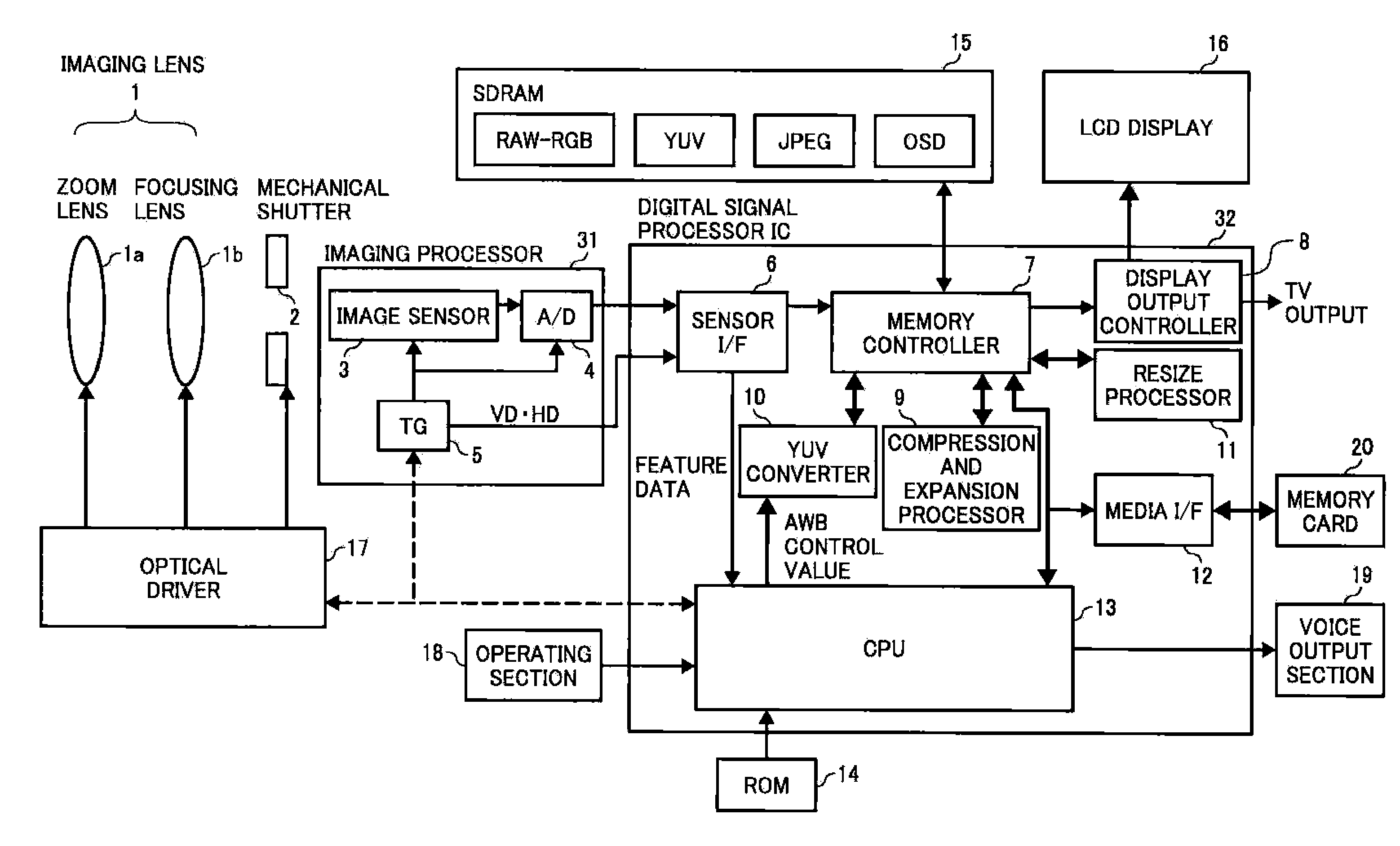
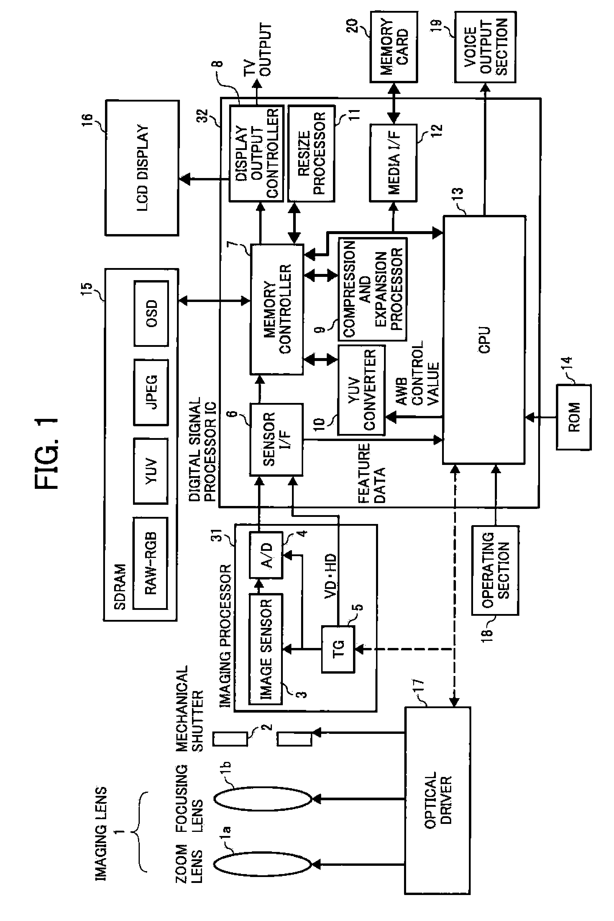
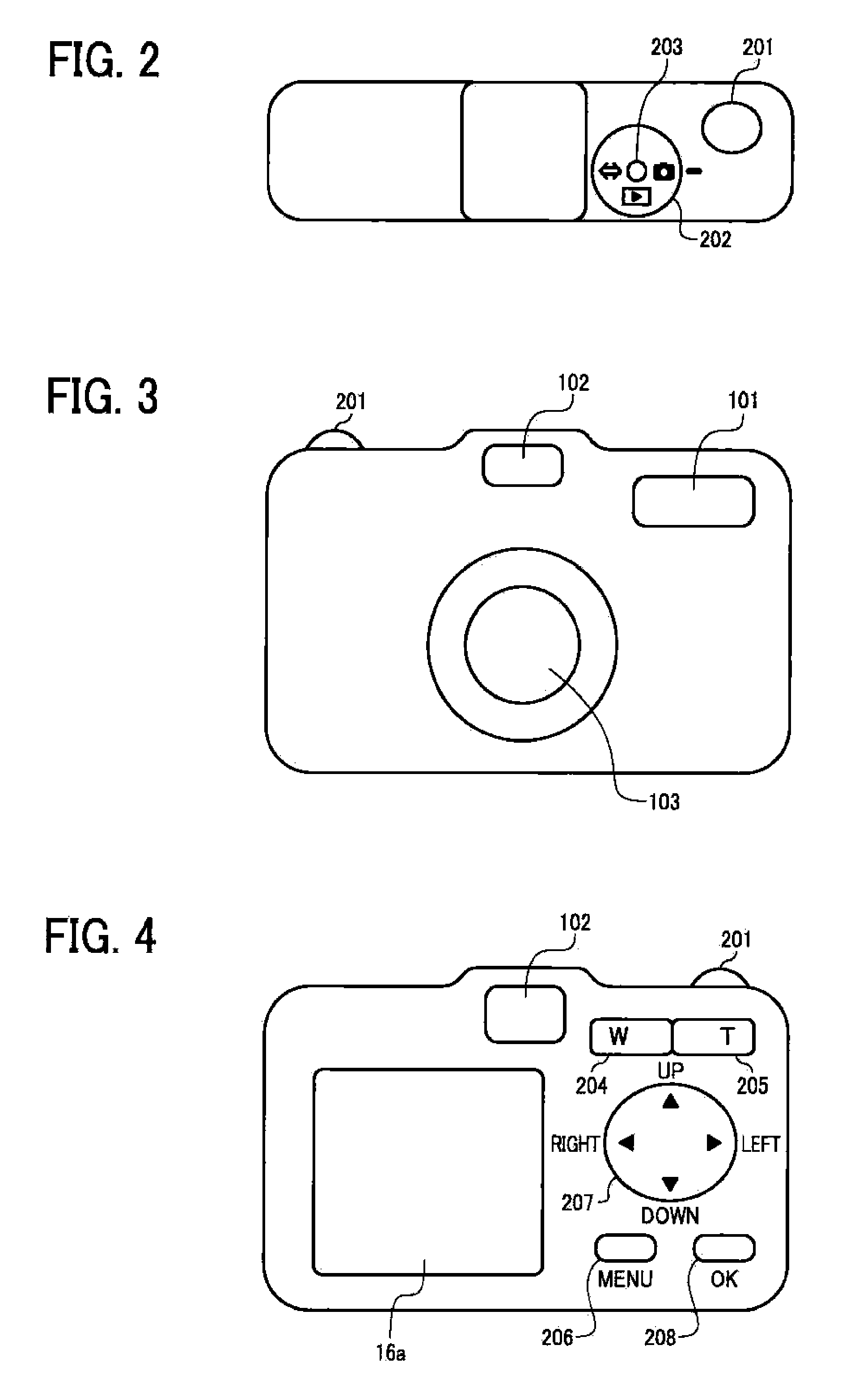
[0141]In this case, the release button 201 (FIGS. 2-4) of the operating section 18 (FIG. 1) is constituted as a two-stage operation release switch. The AF operation is conducted by the first-stage operation, i.e., the half-pressing (release 1), and the photographing process is conducted by the second-stage operation, i.e., the full-pressing (release 2).

[0142]FIG. 13 is one example of ranging results of subject distances by the AF operation, and illustrates on its horizontal axis focused distances of a lens and on its vertical axis AF evaluation values. The example in FIG. 13 is ranging results of subjects having a front person positioned at a distance from 1 m to 2 m, a back person positioned at a dist...

third embodiment

[0152]In the example using the above-described second selecting method, the peak position is sequentially selected by once releasing the half-pressed release button 201, and half-pressing the release button 201 again. If the release button 201 is half-pressed again after selecting all of the detected peak positions, the ranging of the subject distance by the AF operation is re-conducted. Hereinafter, the specific methods of the second selecting method will be described.

[0153]At first, a first method for selecting whether the ranging of the subject distance is re-conducted or it is moved to the detected next peak position will be described. This method performs the selecting according to a change in a subject state.

[0154]As described above, the digital camera described in the present embodiment generally includes a section for obtaining an AF evaluation value and a section for obtaining an RGB integration value which calculates an AE evaluation value and an AWB evaluation value. A fr...

fourth embodiment

[0172]Hereinafter, a fourth embodiment of the present invention will be described.

[0173]As an autofocusing method, an active method using an infrared illumination LED, a passive method using an optical leas and an integral phase difference sensor, and a TTL-AF method, which guides the light after passing through a photographing lens to a phase difference sensor, are known.

[0174]The autofocusing system for use in a recent compact digital camera is generally a contrast system which is a known technique as a conventional autofocusing technique for use in a video camera.

[0175]The operation principle of the contrast system is to photograph a subject while changing the position of a focusing lens by a minimum step, extract a high frequency component of each photographing data (high frequency component of Fourier coefficient when conducting Fourier conversion to image data), and calculate as an AF evaluation value (integration value (average value) of high frequency component of Fourier co...


PUM


Abstract

An imaging device includes an autofocusing section, which moves at least a part of an imaging lens as a focusing lens, and focuses the imaging device on a subject, a photographing distance range setting section, which sets a predetermined distance range including a subject distance to the subject obtained by the autofocusing section as a photographing distance range for photographing, a continuous shooting section, which continuously photographs at a plurality of focused positions in the photographing distance range while moving and stopping the focusing lens according to input of a photographing instruction, and a display section, which displays an image of the subject focused by the autofocusing section and the photographing distance range set by the photographing distance range setting section.

Description

PRIORITY CLAIM[0001]The present application is based on and claims priority from Japanese Patent Applications No. 2007-198979, filed on Jul. 31, 2007, No. 2007-229592, filed on Sep. 4, 2007, and No. 2008-139602, field on May 28, 2008, the disclosures of which are hereby incorporated by reference in their entirety.BACKGROUND OF THE INVENTION[0002]1. Field of the Invention[0003]The present invention relates to an improvement in a continuous shooting function in an imaging device such as a digital still camera. More particularly, the present invention relates to an imaging device, which performs continuous shooting, while moving a focused position, and also to an imaging method in such an imaging device.[0004]2. Description of the Related Art[0005]An electronic imaging device such as a digital still camera (hereinafter, refer to a digital camera) generally includes an autofocusing (AF) system, which focuses a lens, camera, etc., automatically. As an AF control method in such an autofoc...

Claims


Application Information

Patent Timeline
IPC IPC(8): G03B13/32G03B13/18
CPCG02B7/36G03B13/30H04N5/2356H04N5/23212H04N5/23293G03B2217/18H04N23/672H04N23/673H04N23/676H04N23/633H04N23/743
Inventor YOSHIDA, AKIHIROSHIRAISHI, KENJI
Owner RICOH KK
Features
  • Generate Ideas
  • Intellectual Property
  • Life Sciences
  • Materials
  • Tech Scout
  • Unparalleled Data Quality
  • Higher Quality Content
  • 60% Fewer Hallucinations
Learn More