Electrosurgical instrument

Active Publication Date: 2009-02-19
GYRUS MEDICAL LTD
View PDF11 Cites 33 Cited by
  • Summary
  • Abstract
  • Description
  • Claims
  • Application Information

AI Technical Summary

Benefits of technology

[0020]Preferably, the insulation member includes a chamber in which the tissue treatment electrode is received. Conveniently, the tissue treatment electrode comprises an upper portion including the exposed tissue treatment surface, and a lower portion depending therefrom. The chamber within the insulation member is preferably provided with at least one shoulder, adapted to cooperate with the lower portion of the tissue treat

Problems solved by technology

Using high power with a monopolar arrangement is also hazardous, due to the tissue heating that occurs at the return plate, which can cause severe skin burns.
There is also the risk of capacitive coupling between the instrument and patient tissues at the entry point into the body cavity.
However, the depth of effect is directly related to the distance between the two electrodes; and, in applications requiring very small electrodes, the inter-electrode spacing becomes very small, thereby limiting tissue effect and the output power.
Spacing the electrodes further apart would often obscure vision of the application site, and would require a modification in surgical technique to ensure direct contact of both electrodes with the tissue.
One of the obvious limitations with the design is that the tissue treatment electrode must be completely buried in the tissue to enable the return electrode to complete the circuit.
Another problem is one of the orientation even a relatively small change in application angle from the ideal perpendicular contact with respect to the tissue surface, will change the contact area ratio, so that a surgical effect c

Method used


Image

  • Electrosurgical instrument
  • Electrosurgical instrument
  • Electrosurgical instrument

Examples


Embodiment Construction

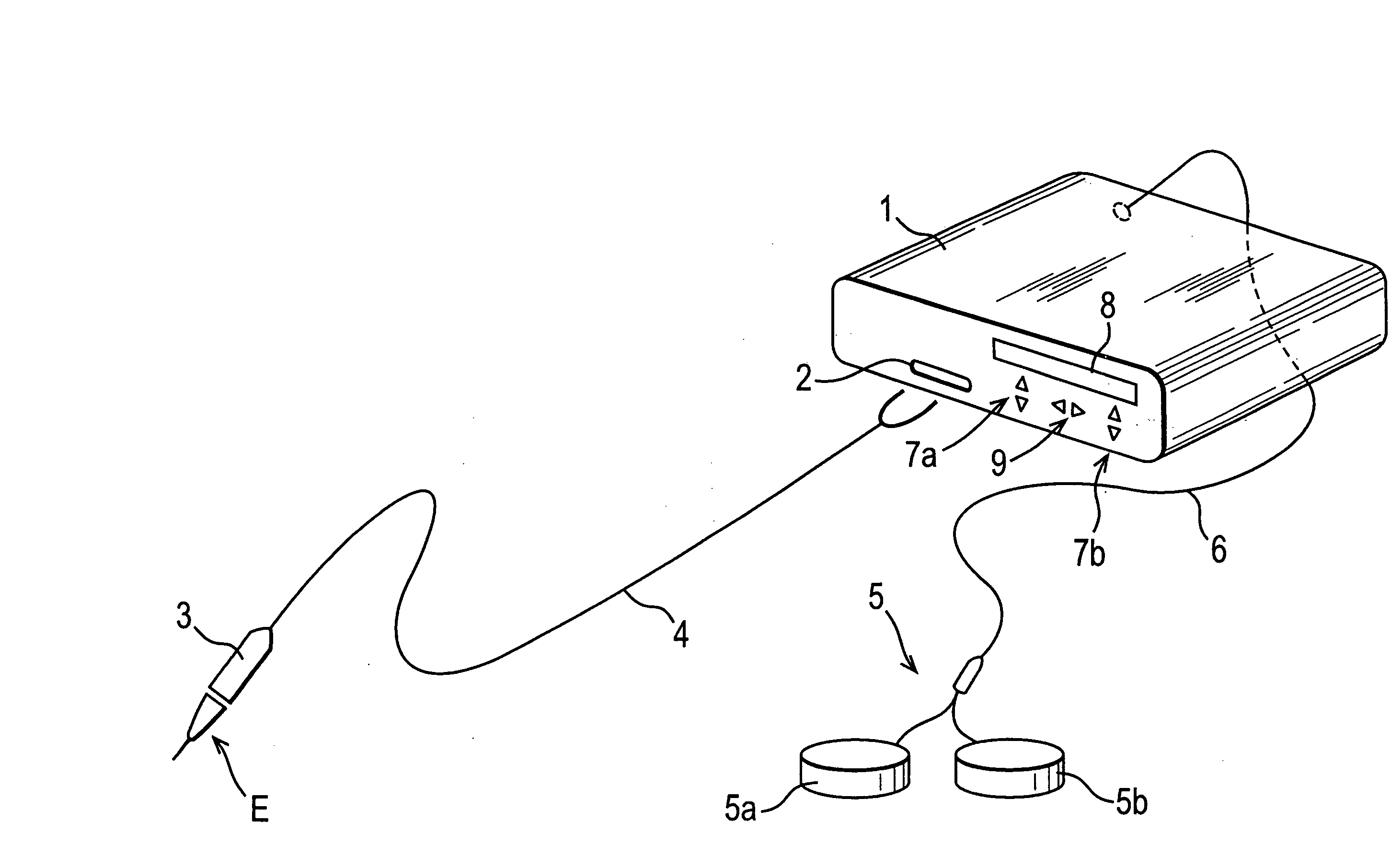
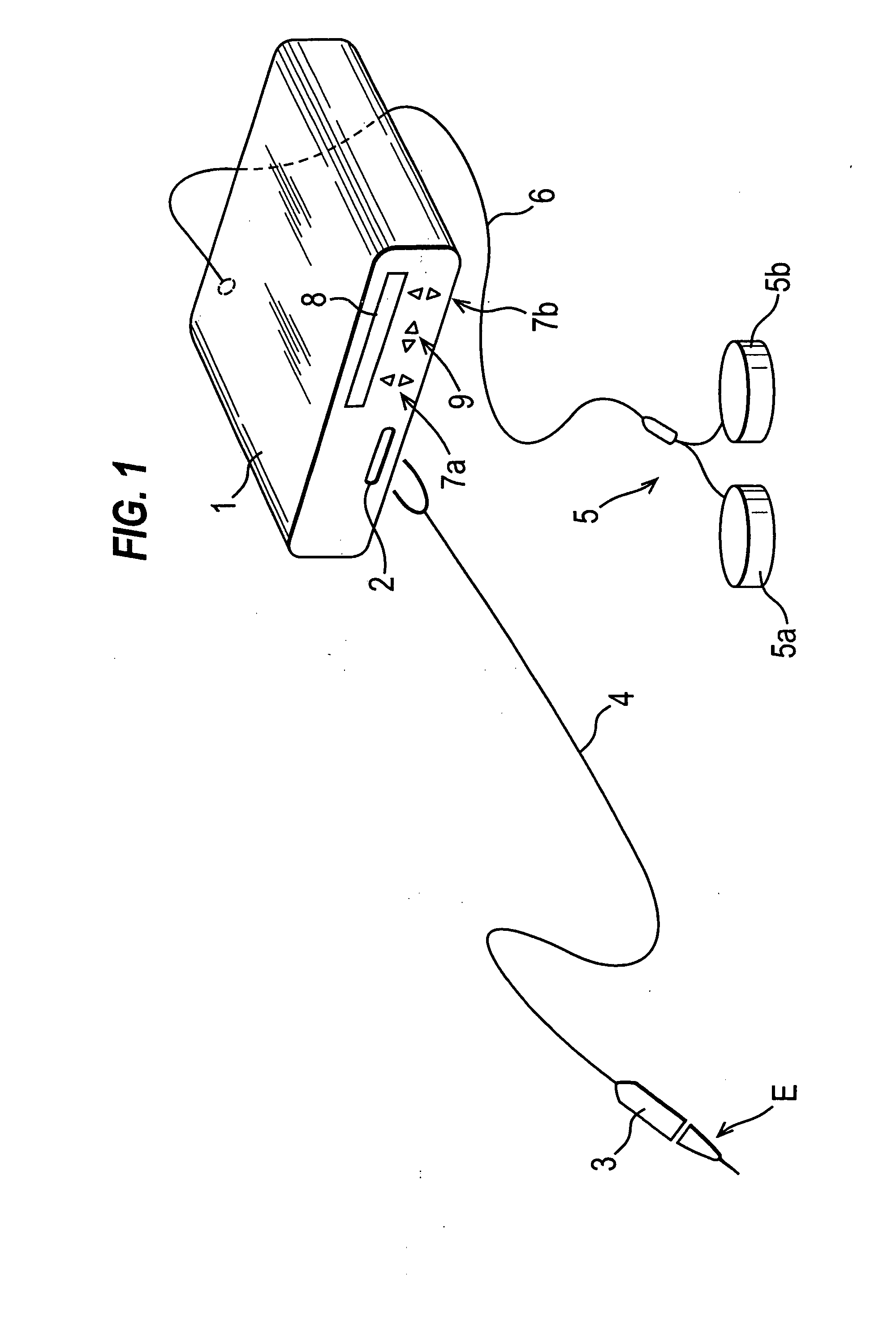
[0053]Referring to the drawings, FIG. 1 shows electrosurgical apparatus including a generator 1 having an output socket 2 providing a radio frequency (RF) output, via a connection cord 4, for an instrument in the form of a handpiece 3. Activation of the generator 1 may be performed from the handpiece 3 via a control connection (not shown) in the cord 4, or by means of a footswitch unit 5 connected separately to the rear of the generator 1 by a footswitch connection cord 6. In the illustrated embodiment, the footswitch unit 5 has two footswitches 5a and 5b for selecting a desiccation mode and a vaporisation mode of the generator 1 respectively. The generator front panel has push buttons 7a and 7b for respectively setting desiccation and vaporisation power levels, which are indicated in a display 8. Push buttons 9 are provided as an alternative means for selection between the desiccation and vaporisation modes.

[0054]The handpiece 3 has an active tip E at its distal end, such as the ac...


PUM


Abstract

An electrosurgical instrument for the treatment of tissue in the presence of an electrically-conductive fluid medium comprises an instrument shaft (10), and an electrode assembly (12) at one end of the shaft. The electrode assembly (12) comprises a tissue treatment electrode (14) and a return electrode (18) which is electrically insulated from the tissue treatment electrode by means of an insulation member (16). The tissue treatment electrode (14) has an exposed surface for treating tissue, and the return electrode (18) has a fluid contact surface so as to define, in use, a conductive fluid path that completes an electrical circuit between the tissue treatment electrode and the return electrode. The tissue treatment electrode (14) is provided with at least one aperture (14a) through which vapour bubbles and/or particulate material can be aspirated from the region surrounding the tissue treatment electrode, and the tissue treatment electrode and the insulation member are disposed such that there is a gap therebetween forming an additional suction channel (25).

Description

RELATED APPLICATIONS[0001]This application claims priority to United Kingdom Application No. 0715152.5, filed 3 Aug. 2007, and claims the benefit of U.S. Provisional Application No. 61 / 006,768, filed 30 Jan. 2008, the entire contents of each of which are hereby incorporated by reference.BACKGROUND OF THE INVENTION[0002]This invention relates to an electrosurgical instrument for the treatment of tissue in the presence of an electrically-conductive fluid medium, to electrosurgical apparatus including such an instrument, and to an electrode unit for use in such an instrument.[0003]Endoscopic electrosurgery is useful for treating tissue in cavities of the body, and is normally performed in the presence of a distension medium. When the distension medium is a liquid, this is commonly referred to as underwater electrosurgery, this term denoting electrosurgery in which living tissue is treated using an electrosurgical instrument with a treatment electrode or electrodes immersed in liquid at...

Claims


Application Information

Patent Timeline
IPC IPC(8): A61B18/18A61B18/14
CPCA61B18/148
Inventor THOMAS, ROLF L.HOOLE, MARTIN P.H.BOWLES, MARK
Owner GYRUS MEDICAL LTD
Why Eureka
Try Eureka