
Method and apparatus for controlling acceleration of a vehicle

a technology of acceleration and apparatus, applied in the direction of braking system, instruments, analogue processes for specific applications, etc., can solve the problems of difficult optimal control, different response characteristics for the change of torque,

Active Publication Date: 2009-02-19
DENSO CORP +1
View PDF24 Cites 22 Cited by
  • Summary
  • Abstract
  • Description
  • Claims
  • Application Information

AI Technical Summary

Benefits of technology

[0008]The present invention has been made in light of the above issues and has as its object to provide an apparatus and system for controlling vehicles, which is able to readily and properly perform the processes of calculating the manipulated variable for each of a motive power generation apparatus and a braking system, as well as matching of these processes, and is able to properly calculate the manipulated variables.
[0010]In this configuration, a sole common requested torque is calculated for the vehicle-mounted motive power generation apparatus and the vehicle-mounted brake apparatuses to feedback-control the actual acceleration to a target acceleration. Then, the requested torque is distributed between the motive power generation apparatus and the brake apparatuses. Thus, in controlling the actual acceleration to a target acceleration, a proper manipulated variable can be readily set for each of the motive power generation apparatus and the brake apparatuses.
[0014]Such a motive power generation apparatus having an internal combustion engine and a transmission tends to have responsiveness lower than that of the brake apparatuses. In order to stabilize the control, the gains should preferably be smaller as the responsiveness becomes lower. Also, the brake apparatuses is usually used during a transient travel time period, while the motive power generation apparatus is usually used during both transient and steady travel time periods. Thus, when the brake apparatuses are not in use, they tend to be preferred that a large manipulated variable is ensured not to be calculated for disturbance. The present invention focuses on this point and allows large gains in the feedback control for the time when the brake apparatuses are used. In this way, suitable gains can be set for both of the time when the brake apparatuses is used and for the time when not used.
[0016]Such fluid-driven brake apparatuses tend to have low responsiveness at the beginning of effecting the braking force. On the other hand, from the viewpoint of stabilizing the control, gains are preferred to be set according to the responsiveness. Thus, when the brake apparatuses begin to effect the braking force, no proper gains may be obtained from the use of the gains obtained after having been enabled to effect a sufficient braking force. In this regard, under the circumstances where the braking force is estimated yet to be sufficient, the above invention can reduce the gains in the feedback control, comparing with those for the time when the brake apparatuses are used. In this way, the feedback control can be performed with the gains suitable for such circumstances.
[0018]Under the circumstances where the braking force is estimated yet to be sufficient, the above invention can reduce the gains in the feedback control, comparing with those for the time when the brake apparatuses is used, by permitting the switching of the gains to be delayed in the feedback control. Thus, when the braking force is insufficient after the start of use of the brake apparatuses, the feedback control can be performed with the gains for the time when the brake apparatuses is not used, that is, the gains smaller than those for the time when the brake apparatuses is used. In addition, under the conditions where the braking force is insufficient, the feedback control can be performed with proper gains.
[0022]It takes time for such fluid-driven brake apparatuses to sufficiently effect the braking force. Accordingly, the braking force may be insufficient immediately after the start of use of the brake apparatuses. In this regard, the above configuration permits the pressure of the fluid to be increased in advance, if a request for using the braking force is estimated to be issued. In this way, a sufficient braking force can be ensured immediately after the start of use of the braking force.

Problems solved by technology

However, in general, response characteristics for the change of the requested torque may be different between the motive power generation apparatus and the brake apparatuses.
Thus, if the gains in the feedback control are common between the time when the brake apparatuses are used and the time when not used, it may be difficult to perform optimal control.

Method used


Image

  • Method and apparatus for controlling acceleration of a vehicle
  • Method and apparatus for controlling acceleration of a vehicle
  • Method and apparatus for controlling acceleration of a vehicle

Examples


first embodiment

[0043]With reference to the accompanying drawings, hereinafter will be described a vehicle control apparatus according to a first embodiment of the present invention.

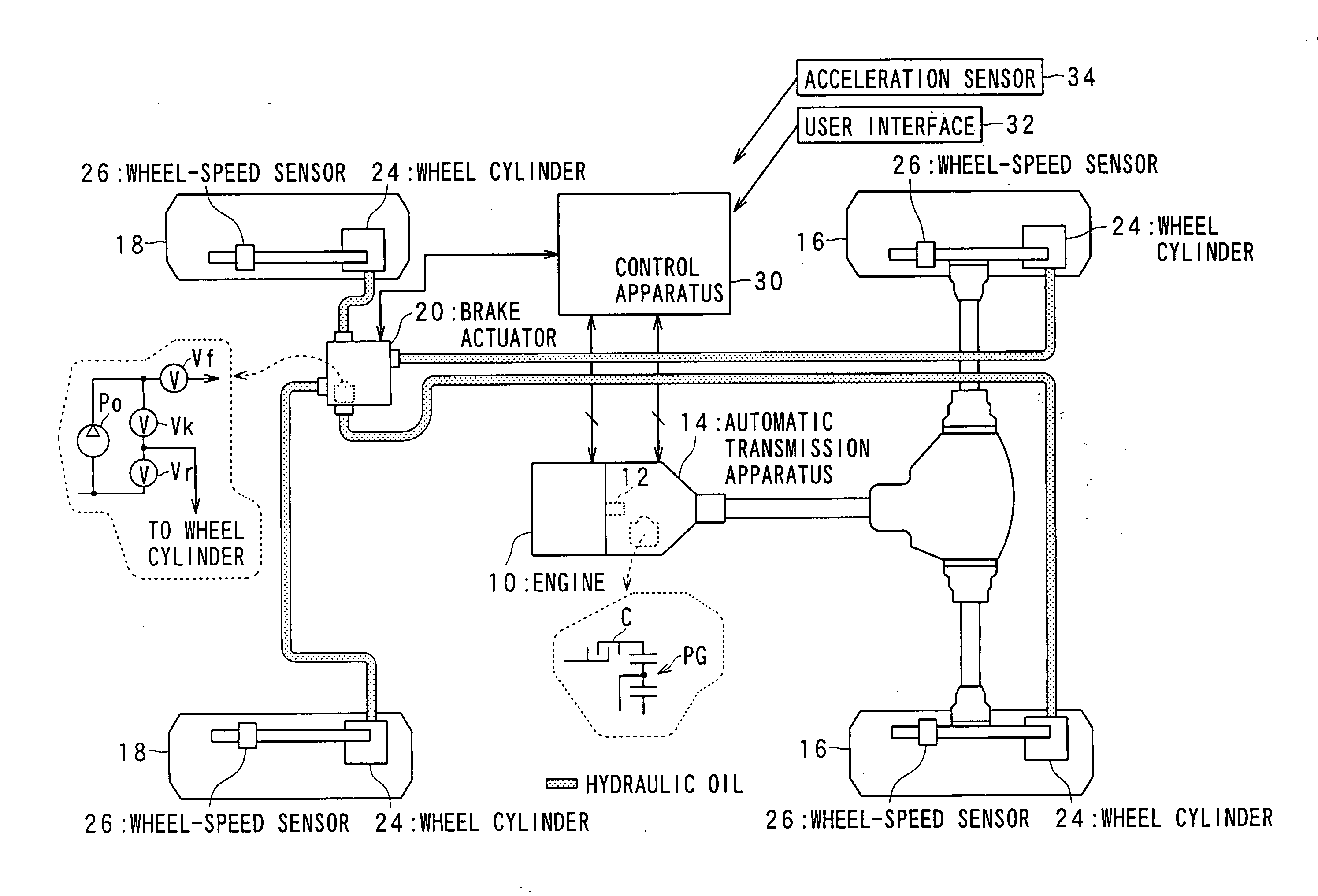
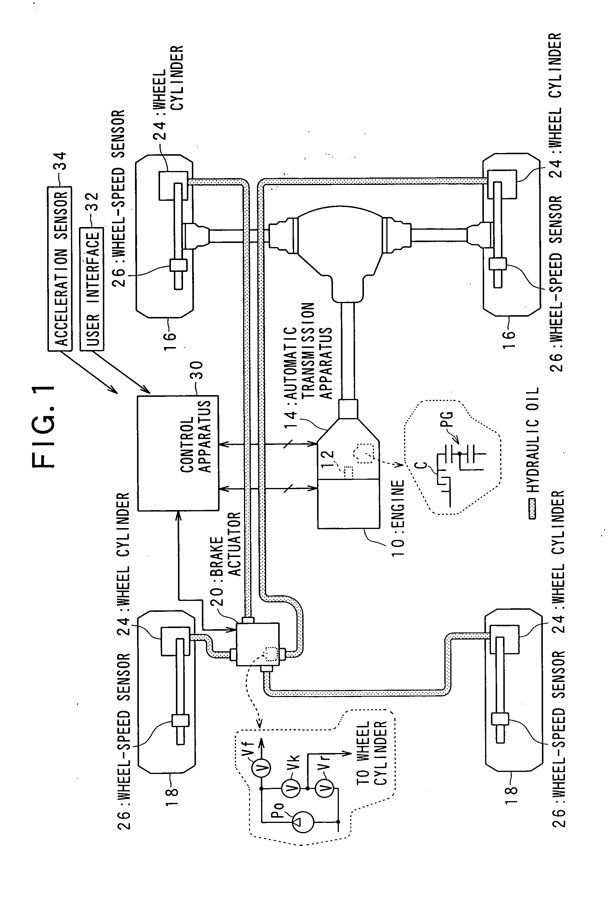
[0044]FIG. 1 illustrates a general configuration of the vehicle control system, according to the present embodiment.

[0045]An engine 10, a gasoline powered internal combustion engine, includes a crank shaft 12 to which an automatic transmission apparatus 14 is connected. The automatic transmission apparatus 14 is provided with a torque converter and a planetary gear automatic transmission. In the planetary gear automatic transmission, any of a plurality of power transmission paths formed by planetary gears PG is selected, depending on the engagement conditions of a clutch C and a brake (not shown) as friction elements. The planetary gear automatic transmission is adapted to realize a gear ratio according to the selected power transmission path. The torque of the crank shaft 12 of the engine 10 is changed by the automatic...

second embodiment

[0109]With reference to the drawings, hereinafter will be described a second embodiment of the present invention, focusing on the differences from the first embodiment. In the present embodiment, the identical or similar components and steps to those in the first embodiment are given the same reference numerals for the sake of omitting explanation.

[0110]In the present embodiment, at the start of use of the brake actuator 20, switching of the gains in the feedback control is delayed. Thus, the gains can be prevented from becoming excessively large immediately after the start of use of the brake actuator 20, when braking force Is insufficient.

[0111]FIG. 14 shows a series of processes associated with the manipulation of the brake actuator 20, according to the present embodiment. These processes are repeatedly performed by the control apparatus 30 at a predetermined time interval, for example.

[0112]As shown, in the present embodiment, when the brake flag “fB” is in an on-state, the brak...


PUM


Abstract

A control apparatus controls acceleration of a vehicle provided with a motive power generation apparatus and brake apparatuses. For the control, the control apparatus comprises calculation and actuating blocks. The calculation block calculates torque to be requested, based on a difference between an actual value of the acceleration and a target value thereof and a gain for feedback controlling the actual value of the acceleration to the target value thereof. The gain is differentiated in value between in a first case in which the brake apparatuses are used for the feedback control and a second case in which the brake apparatuses are not used for the feedback control. The actuating block actuates the motive power generation apparatus and the brake apparatuses based on the calculated torque. The value of the gain in the first case is made larger than the value of the gain in the second case.

Description

CROSS-REFERENCE TO RELATED APPLICATION[0001]This application is based on and claims the benefit of priority from earlier Japanese Patent Application No. 2007-209244 filed Aug. 10, 2007, the description of which is incorporated herein by reference.BACKGROUND OF THE INVENTION[0002]1. Technical Field of the Invention[0003]The present invention relates to an apparatus and system for controlling vehicles, which is able to feedback-control an actual vehicle acceleration to a target acceleration.[0004]2. Related Art[0005]This type of control apparatus is disclosed, for example, in Japanese Patent Laid-Open No. 2006-506270. According to the technique disclosed in this literature, the actual acceleration and a target acceleration of the vehicle are inputted to an operating means for operating the vehicle-mounted engine and an operating means for operating the brake, in order to feedback-control the actual vehicle acceleration to the target acceleration. Under such control, requests from the ...

Claims


Application Information

Patent Timeline
Patent Type & Authority Applications(United States)
IPC IPC(8): G06F7/00B60T7/12B60T8/17B60T8/174B60W10/00B60W10/04B60W10/06B60W10/10B60W10/11B60W10/115B60W10/18B60W10/188B60W30/00B60W30/14B60W50/06F16H59/14F16H59/48F16H61/02F16H61/68F16H61/684F16H61/686F16H63/50
CPCB60W10/06B60W10/11B60W10/184B60W30/16Y02T10/56B60W2710/10B60W2710/105B60W2710/182B60W2720/106B60W2710/0666B60W2050/0012B60W2050/0031Y02T10/40
Inventor NAKAI, YASUHIROKUMABE, HAJIMEFUKUDA, SHOTARONIWA, SATOSHIKODAMA, HIROYUKIKADOWAKI, KAZUNORIOSAKI, SHINTARO
Owner DENSO CORP
Learn More