Rapid determination of fatigue failure based on temperature evolution

a temperature evolution and fatigue failure technology, applied in the field of material science and engineering, can solve the problems of increasing the strength of the structure or the component, reducing the service life of the structure, and prone to crack formation of all structures and machinery components undergoing fatigue loading, so as to avoid catastrophic failure and effectively utilize the

Inactive Publication Date: 2009-02-19
BOARD OF SUPERVISORS OF LOUISIANA STATE UNIV & AGRI & MECHANICAL COLLEGE
View PDF0 Cites 35 Cited by
  • Summary
  • Abstract
  • Description
  • Claims
  • Application Information

AI Technical Summary

Benefits of technology

[0014]The surface temperature is related to the number of cycles to failure. In particular, we have determined that the slope of the temperature curve at the beginning of the test can be effectively utilized as an index for fatigue life prediction. Using this technique, the remaining life of a machine can be predicted and catastrophic failure can be avoided. This technique can be applied by installing a sensor, in-situ, and testing the component while it is undergoing the fatigue load. The life expectancy estimate is obtained while the object is in use, which provides an advantage over techniques that require stopping the operation of the machine.

Problems solved by technology

All structures and machinery components undergoing fatigue loading are prone to crack formation and its subsequent growth that increases with time.
When a crack is formed, the strength of the structure or the component is decreased and can no longer function in the intended manner for which it was designed for.
Moreover, the residual strength of the structure decreases progressively with increasing crack size.
Eventually, after a certain time the residual strength becomes so low that the structure fails [1].
On the contrary, in the case of cyclic loading, where the stress is one of fatigue, the material arrives at the condition of local yielding (micro-plasticization) and a micro-crack is generated.
Hence, the repeated application of the stress leads to the crack propagation until, eventually, the condition of failure is reached and the specimen breaks.

Method used


Image

  • Rapid determination of fatigue failure based on temperature evolution
  • Rapid determination of fatigue failure based on temperature evolution
  • Rapid determination of fatigue failure based on temperature evolution

Examples


Embodiment Construction

[0037]An extensive experimental program has been performed that involves testing pertinent types of materials of interest. These materials are used in systems that experience bending fatigue, torsion fatigue, tension / compression, as well as combined mode. A fatigue testing apparatus was used to apply cyclic bending and torsion load. The specimens used were fabricated from Aluminum and Stainless Steel. A full field surface temperature was monitored by means of an infrared camera. FIG. 3A shows the test platform used for bending fatigue testing.

[0038]The fatigue testing apparatus used is a compact bench mounted unit with a variable speed motor, variable throw crank connected to the reciprocating platen, a failure cut off circuit in a control box, and a cycle counter. An available option is a torsion and axial tester. FIG. 3A shows a photograph of the experimental setup used in this study to applying cyclic bending load. Fatigue tests were run until specimen complete separation. The ma...


PUM


Abstract

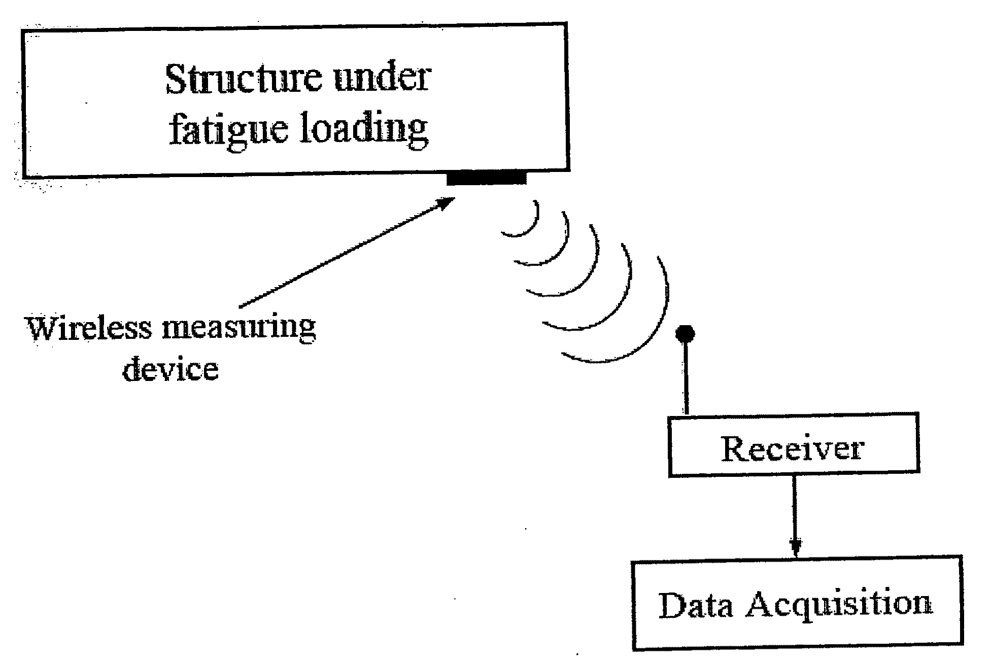
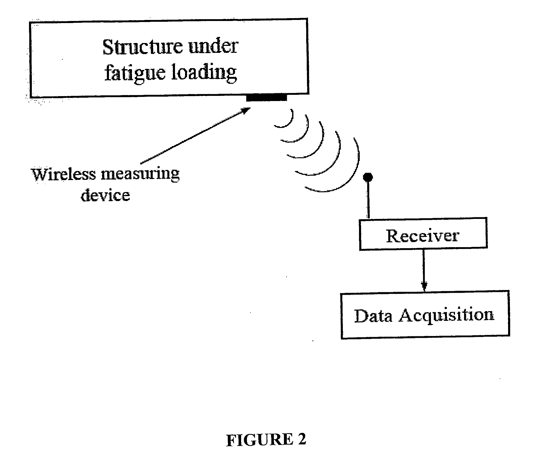
A method and apparatus are disclosed for predicting the service life of a metallic structure subjected to cyclic loading. Such structures experience fatigue, which can lead to failure after a number of loading cycles. The disclosed invention allows for an accurate prediction of the number of cycles to failure for a metallic structure by observing the slope of the rise in surface temperature of the structure after the cyclic loading has begun. The method of this invention provides early and accurate predictions of service life and does not require destructive testing. The method and apparatus of the present invention may be installed on working equipment, thus providing service life predictions for materials in real world use. The invention uses an empirically derived relationship that was confirmed using analytical relationships and material properties. The derived formula uses two constants that may be determined empirically using a disclosed process. The constants also may be estimated mathematically. The apparatus may include a wireless temperature sensor mounted on the metallic structure of interest and a data analysis unit to perform the needed calculations.

Description

PRIORITY CLAIM UNDER 35 U.S.C. § 119(e)[0001]This application claims the benefit of U.S. Provisional Application No. 60 / 956,292, filed on Aug. 16, 2007.FIELD OF THE INVENTION[0002]The invention relates to materials science and engineering, and in particular to the prediction of the service life of a metallic structure exposed to cyclic loading.BACKGROUND OF THE INVENTION[0003]All structures and machinery components undergoing fatigue loading are prone to crack formation and its subsequent growth that increases with time. When a crack is formed, the strength of the structure or the component is decreased and can no longer function in the intended manner for which it was designed for. Moreover, the residual strength of the structure decreases progressively with increasing crack size. Eventually, after a certain time the residual strength becomes so low that the structure fails [1]. It is, therefore, of paramount importance to be able to predict the rate of decline in the component's r...

Claims


Application Information

Patent Timeline
Patent Type & Authority Applications(United States)
IPC IPC(8): G06F19/00
CPCC21D11/00G01N3/32G01N25/72G01N2203/0694G01N2203/0066G01N2203/0222G01N2203/0647G01N2203/0064
Inventor DAREHBIDI, MEHDI AMIRIKHONSARI, MICHAEL M.
Owner BOARD OF SUPERVISORS OF LOUISIANA STATE UNIV & AGRI & MECHANICAL COLLEGE
Why Eureka
Try Eureka