Holding and sealing material and manufacturing method thereof

a technology of holding and sealing material, which is applied in the direction of sewing, machines/engines, separation processes, etc., can solve the problems of affecting the work efficiency of the mounting work, the risk of deteriorating the working environment of the mounting work area, and the inability to adequately reduce the flying amount of inorganic fibers, etc., to suppress the breakage of inorganic fibers, the effect of excellent extensibility

Active Publication Date: 2009-02-26
IBIDEN CO LTD
View PDF22 Cites 46 Cited by
  • Summary
  • Abstract
  • Description
  • Claims
  • Application Information

AI Technical Summary

Benefits of technology

[0017]Furthermore, in the manufacturing method of the holding and sealing material of the preferred embodiment of the present invention, an organic binder with a low glass transition point Tg (° c) of less than or equal to 5° C. is used as the organic fiber. Therefore, the organic binder attached to the holding and sealing material can exhibit high motility rubbery state at room temperature (e.g. temperature which is equal to or more than glass transition point of the organic binder). Accordingly, at a time of mounting the holding and sealing material in the catalyst carrier and the shell, the organic binder can combine the inorganic fibers each other of the mat-like material and also can exhibit excellent extensity, and it is possible to absorb damage such as a shock or the like given to the holding and sealing material. Thus, it is possible to suppress a break of the inorganic fibers of the holding and sealing material, and to prevent the inorganic fibers from flying in all directions from the holding and sealing material. Therefore, the workers can comfortably work without wearing the antidust mask or the like and it is possible to keep the working environment of the working area for the mounting work good.
[0018]As described above, in the holding and sealing material obtained by the manufacturing method of the preferred embodiment of the present invention, the organic binder can suppress a break of the inorganic fibers of the mat-like material and can hold the inorganic fibers. Therefore, the holding and sealing material can prevent the inorganic fibers from flying in all directions without increasing an amount of an inorganic binder.

Problems solved by technology

Therefore, there is a risk of deteriorating a working environment of a working area for the mounting work, and it is necessary for a worker to work with wearing an antidust mask or the like.
However, it was impossible to adequately reduce a flying amount of inorganic fibers even by a conventional holding and sealing material 91 whose fiber diameter is controlled.
Therefore, there is a risk that a part of the inorganic fibers flies in all directions in the air while at work and a working environment is deteriorated.

Method used


Image

  • Holding and sealing material and manufacturing method thereof
  • Holding and sealing material and manufacturing method thereof
  • Holding and sealing material and manufacturing method thereof

Examples


embodiments

Embodiment 1

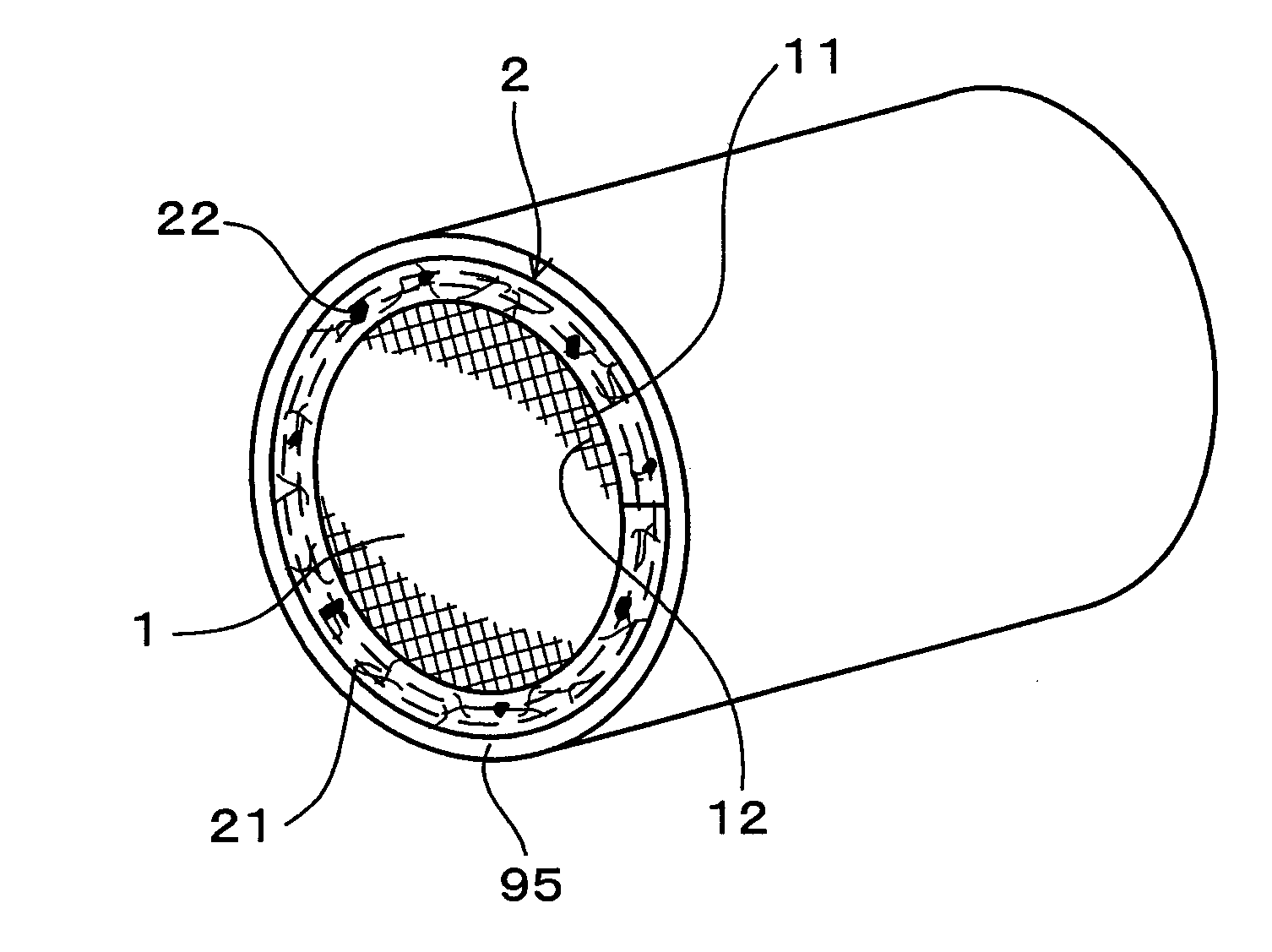
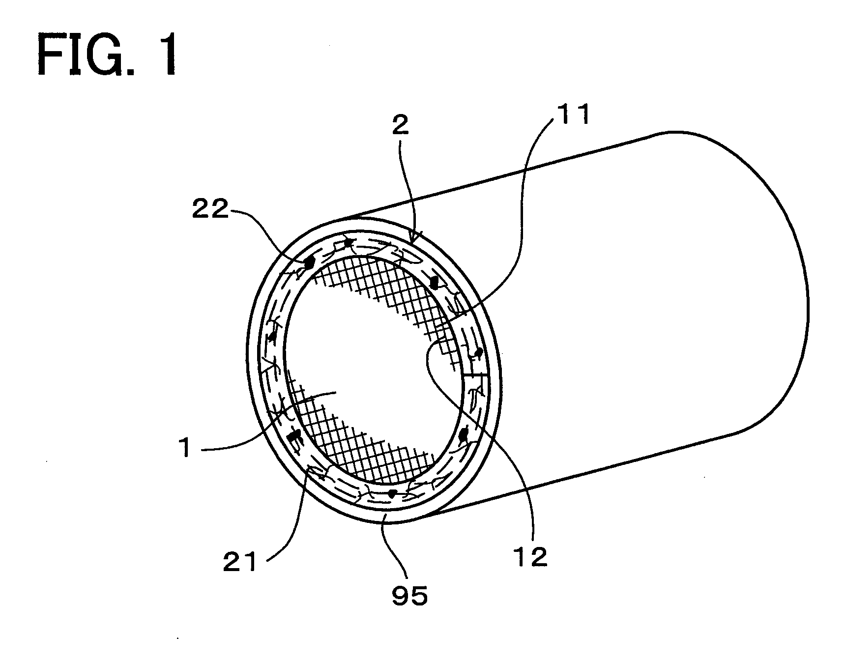
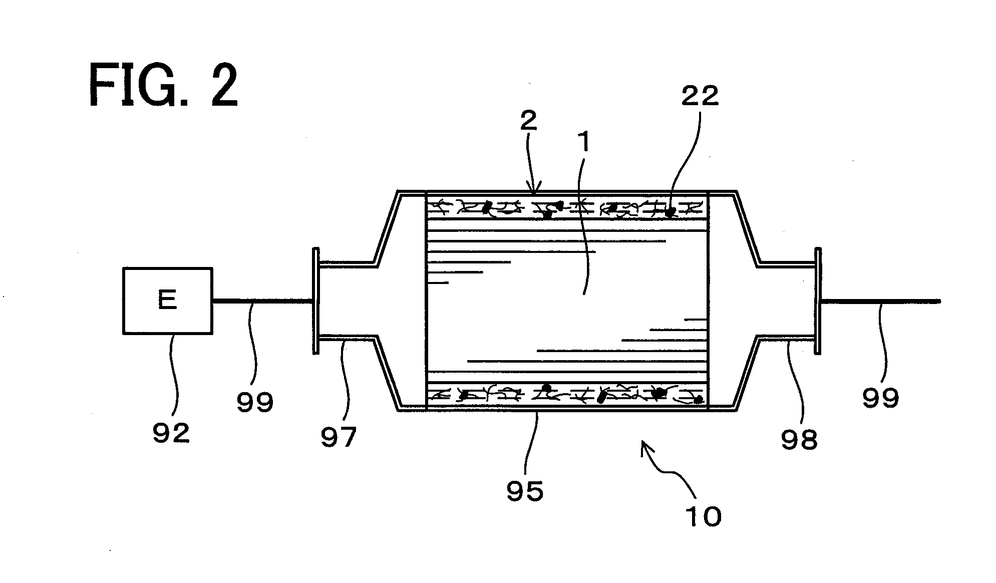
[0073]Next, the holding and sealing material relates to the embodiment in the present invention is explained with FIG. 1 to FIG. 4.

[0074]As shown in FIG. 1 and FIG. 2, the holding and sealing material 2 of the present embodiment is used as being disposed on between the catalyst carrier 1 and the shell 95 which covers outer of the catalyst carrier 1 in the catalytic converter for purifying an exhaust gas 10. In the holding and sealing material 2, the mat-like material is formed by arranging the inorganic fibers in mat shape, and the organic binder 22 with the glass transition point Tg (° c) of less than or equal to 5° C. is attached to the mat-like material 21 (refer to FIGS. 3(A) and (B)).

[0075]Details are described below.

[0076]As the catalyst carrier 1, a cordierite carrier whose a transverse sectional surface is formed in a honeycomb shape. A lot of rectangular holes 11 are provided along an axial direction in this catalyst carrier 1. Further, a lot of honeycomb walls ...

embodiment 2

[0095]In the present embodiment, a drop test was conducted as described below in order to make sure of difficulty of flying the inorganic fibers contained in the holding and sealing material in all directions in the air.

[0096]Specifically, as well as embodiment 1, a plural number of holding and sealing materials (sample E1 to sample E4, sample C1 to sample C4) was manufactured by using the emulsion containing the organic binders having different glass transition point (Tg). And then, they were dropped from the specific height and difficulty of flying the inorganic fibers in all directions in the air at this time was evaluated.

[0097]To be more precise, eight kinds of holding and sealing material which are sample E1 to sample E4 and sample C1 to sample C4 were manufactured.

[0098]Sample E1 was manufactured by infiltrating with acrylonitrile-butadiene copolymer latex (the glass transition point Tg of the organic binder: −21° C., the emulsion particle diameter: 50 nm, the density of the ...


PUM

PropertyMeasurementUnit
glass transition point Tgaaaaaaaaaa
particle diameteraaaaaaaaaa
glass transition point Tgaaaaaaaaaa

Abstract

The present invention relates to a holding and sealing material 2 set between a catalyst carrier 1 and a shell 95 which covering the outside of the catalyst carrier 1 in a catalytic converter for purifying an exhaust gas and manufacturing method thereof. An organic binder 22 on the holding and sealing material 2 has the glass transition point Tg (° c) of less than or equal to approximately 5° C. In addition, an infiltrating step and a drying step are conducted during the manufacturing. In the infiltrating step, the mat-like material is infiltrated with emulsion containing the organic binder. In the drying step, the mat-like material containing the emulsion is dried.

Description

CROSS-REFERENCES TO RELATED APPLICATIONS[0001]The application is a divisional of and claims the benefit of priority under 35 U.S.C. §120 from U.S. Ser. No. 11 / 444,484, filed Jun. 1, 2006, and claims the benefit of priority under 35 U.S.C. §119 from Japanese Patent Application No. 2005-171221, filed Jun. 10, 2005, entitled “HOLDING AND SEALING MATERIAL AND MANUFACTURING METHOD THEREOF”. The contents of this application are incorporated herein by reference in their entirety.BACKGROUND OF THE INVENTION[0002]1. Field of the Invention[0003]The present invention relates to a holding and sealing material of a catalytic converter for purifying an exhaust gas discharged from an internal combustion engine or the like.[0004]2. Discussion of the Background[0005]As shown in FIG. 5, conventionally, a catalytic converter 90 for purifying an exhaust gas has been used for purifying an exhaust gas discharged from an internal combustion engine 92 or the like. The catalytic converter 90 has a catalyst ...

Claims


Application Information

Patent Timeline
Patent Type & Authority Applications(United States)
IPC IPC(8): B01D50/00B21D51/16
CPCB01D53/9454Y10T29/49345Y02T10/22F01N3/2853Y10T428/249964Y10T442/2926Y02T10/12F01N3/28F01N3/20F01N3/24
Inventor EGUCHI, MASAYUKI
Owner IBIDEN CO LTD
Why Eureka
Try Eureka