Optical transceiver with a plurality of optical subassemblies electrically connected by integrated FPC board with a substrate

a technology of optical subassemblies and optical transceivers, which is applied in the direction of semiconductor lasers, instruments, semiconductor/solid-state device details, etc., can solve the problems of complex optical coupling between components, electrical connection between transmitters and receivers with electronic circuits that are also installed within the standard housing, and unfitness of conventional transceivers to a standard transceiver. , to achieve the effect of simple bendability, reducing manufacturing costs, and enhancing reliability

Active Publication Date: 2009-02-26
SUMITOMO ELECTRIC IND LTD
View PDF20 Cites 41 Cited by
  • Summary
  • Abstract
  • Description
  • Claims
  • Application Information

AI Technical Summary

Benefits of technology

[0012]Because the plurality of subassemblies is electrically connected to the substrate with only one FPC board having branches corresponding to each subassemblies and the unified portion attached to the substrate, the drawing of the FPC board becomes simple and neat, which may enhance the reliability and reduce the manufacturing cost.
[0013]The FPC board of the invention may provide creases in respective branches to make it simple to bend the FPC board to connect the end of the branch with the subassembly, and each crease may accompany with a notch in the edge of the FPC board. The FPC board may further provide an end in each branch with a rigid substrate attached thereto, where the end of the branch and the rigid substrate provide via holes, into which the lead pins of the optical subassembly are inserted. The shape of the via hole may be an extended oval bent along a circle whose center is substantially same as the center position of the lead pins. This arrangement of the end of the branch, in particular, the shape and positions of the via holes in the end, may enhance a tolerance of the assembly between the FPC board and the optical subassembly.

Problems solved by technology

These conventional transceivers are unfit to a standard transceiver, because the optical arrangement in those transceivers are primary determined by the arrangement or the function of the wavelength selective filter.
In such optical transceiver with a plurality of receivers, transmitters and filters, it is necessary to arrange those components in compact to apply the standard housing, which makes the optical coupling between components complex and the electrical connection between transmitters and receivers with the electronic circuit that is also installed within the standard housing has to be restricted.
However, because each optical device is fixed to the optical unit, 11 or 12, with a specific angle independent of each device, the drawing of the FPC boards becomes quite complex, which not only degrades the reliability but also prolongs the manufacturing time.

Method used


Image

  • Optical transceiver with a plurality of optical subassemblies electrically connected by integrated FPC board with a substrate
  • Optical transceiver with a plurality of optical subassemblies electrically connected by integrated FPC board with a substrate
  • Optical transceiver with a plurality of optical subassemblies electrically connected by integrated FPC board with a substrate

Examples


Embodiment Construction

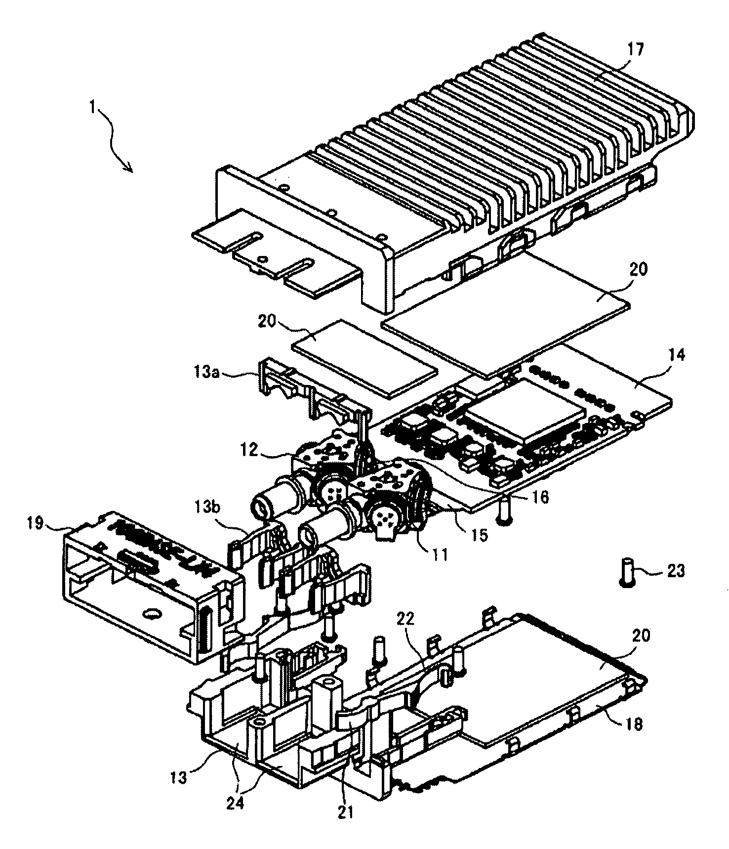
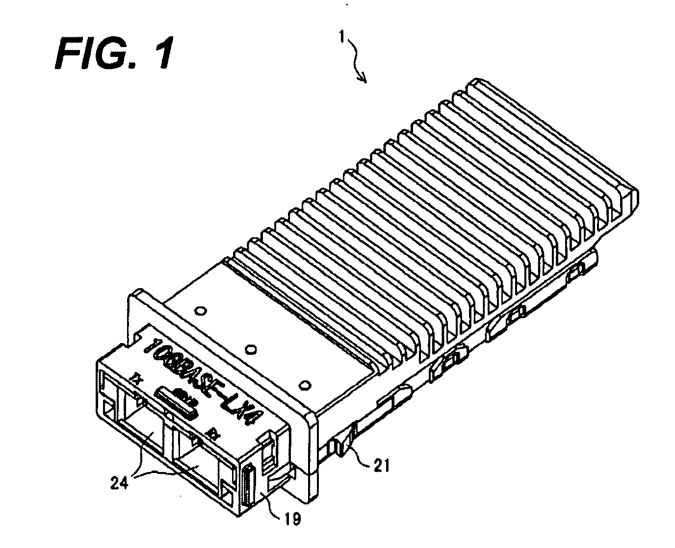
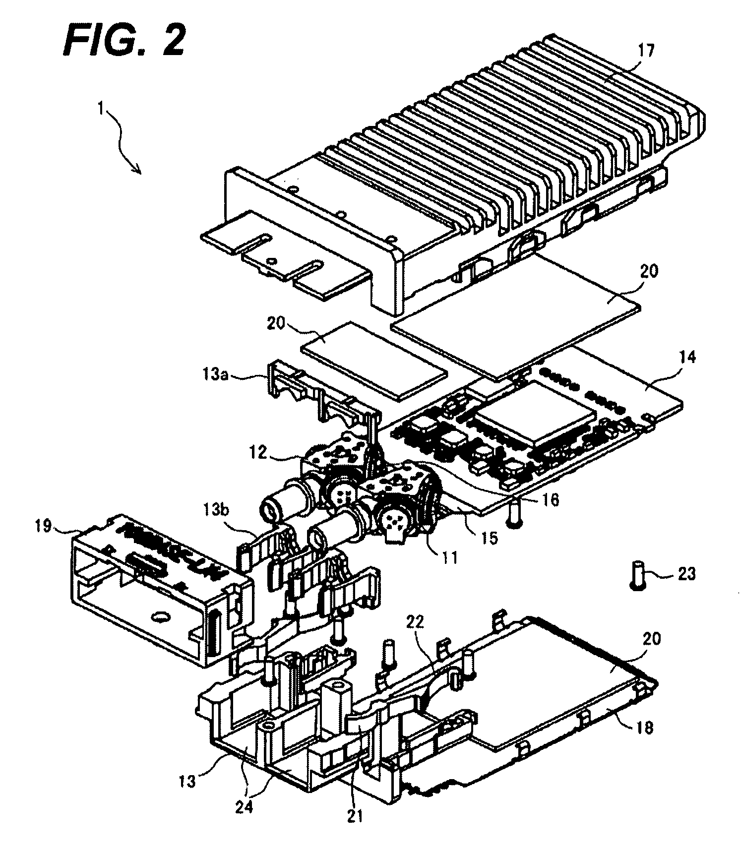
[0024]FIG. 1 is an appearance of an optical transceiver according to an embodiment of the present invention. The transceiver 1 has a shape following the standard of the XENPAK or the X2, and is to be inserted into an opening provided in the faceplate of the host equipment. The transceiver 1 provides a latch tab 21 in the sides, which mates with an opening formed on a metal rail on the substrate of the host equipment. This mating of the latch tab 21 with the opening sets this transceiver within the host equipment.

[0025]On the front end of the transceiver is provided with an optical receptacle 24 into which an external optical connector is to be inserted. In the description below, the front of the transceiver 1 is a side where the receptacle is formed, while the rear thereof is a side to be inserted into the opening of the face plate of the host equipment. The transceiver 1 further provides a grip 19 that releases the latching between the latch tab 21 with the opening of the rail by s...


PUM


Abstract

The present invention provides an optical transceiver with a function of the wavelength division multiplexing. The transceiver includes a receiver optical unit, a transmitter optical units and a substrate. Both optical unit includes a plurality of receiver optical subassemblies (ROSAs) or a plurality of transmitter optical subassemblies (TOSAs) and a plurality of wavelength selective filters. The ROSAs or the TOSAs in respective optical units is electrically connected with the circuit on the substrate by the flexible printed circuit (FPC) board with a plurality of branches, each connected to the ROSAs or the TOSAs, and a connecting portion fixed to the substrate.

Description

BACKGROUND OF THE INVENTION[0001]1. Field of the Invention[0002]The present invention relates to an optical transceiver, in particular, the invention relates to an optical transceiver with a function of a wavelength division multiplexing (hereafter denoted as WDM).[0003]2. Relater Prior Art[0004]A new type of an optical transceiver has been proposed in which a plurality of receiver optical subassemblies (hereafter denoted as ROSA) and transmitter optical subassemblies (hereafter denoted as TOSA) are installed, and such transceiver may realize the WDM system with relatively lower cost. This type of the optical transceiver is replaceable to the host system arranging a plurality of optical transceivers each providing single optical channel.[0005]The United States Patent published as 2003 / 0064833A has disclosed an optical transceiver built in two receivers (Rx), single transmitter (Tx) and wavelength selective filters that transmit light with specific wavelength range and reflects light...

Claims


Application Information

Patent Timeline
Patent Type & Authority Applications(United States)
IPC IPC(8): H04J14/02H01L31/02H01S5/022H04B10/25H04B10/40H04B10/50H04B10/60H04B10/67
CPCG02B6/4246H04B10/40H05K2201/10121H05K1/189H05K2201/053H05K1/147
Inventor OKI, KAZUSHIGEKASAI, OSAMIKAMISUGI, HIDEAKIKURASHIMA, HIROMIMURAKAMI, YASUNORI
Owner SUMITOMO ELECTRIC IND LTD
Why Eureka
Try Eureka