Sound Source Separation Device, Speech Recognition Device, Mobile Telephone, Sound Source Separation Method, and Program

a separation device and speech recognition technology, applied in the direction of transducer casing/cabinet/support, electrical transducer, instruments, etc., can solve the problems of affecting the estimation accuracy, the filter cannot perform well, and the production cost is increased

Active Publication Date: 2009-02-26
ASAHI KASEI KK
View PDF4 Cites 184 Cited by
  • Summary
  • Abstract
  • Description
  • Claims
  • Application Information

AI Technical Summary

Benefits of technology

[0041]According to the present invention, a first beamforming processing and a second beamforming processing are performed for attenuating sound source signals arriving from predetermined directions symmetrical with respect to a perpendicular line to a straight line connecting two microphones respectively by performing operations using two weighted coefficients which are complex conjugate to each other in a frequency domain, thereby the sound source signals arriving from the predetermined directions symmetrical with respect to the perpendicular line to the straight line connecting two the microphones respe...

Problems solved by technology

However, there are problems about increase of production cost, when a reference signal should be played, how to determine whether or not a recorded signal contains only a reference signal, and so on.
Paying attention to operation of an adaptive filter, in general, if there is a high correlation between a reference signal and a target signal, estimation process of the adaptive fi...

Method used


Image

  • Sound Source Separation Device, Speech Recognition Device, Mobile Telephone, Sound Source Separation Method, and Program
  • Sound Source Separation Device, Speech Recognition Device, Mobile Telephone, Sound Source Separation Method, and Program
  • Sound Source Separation Device, Speech Recognition Device, Mobile Telephone, Sound Source Separation Method, and Program

Examples


first embodiment

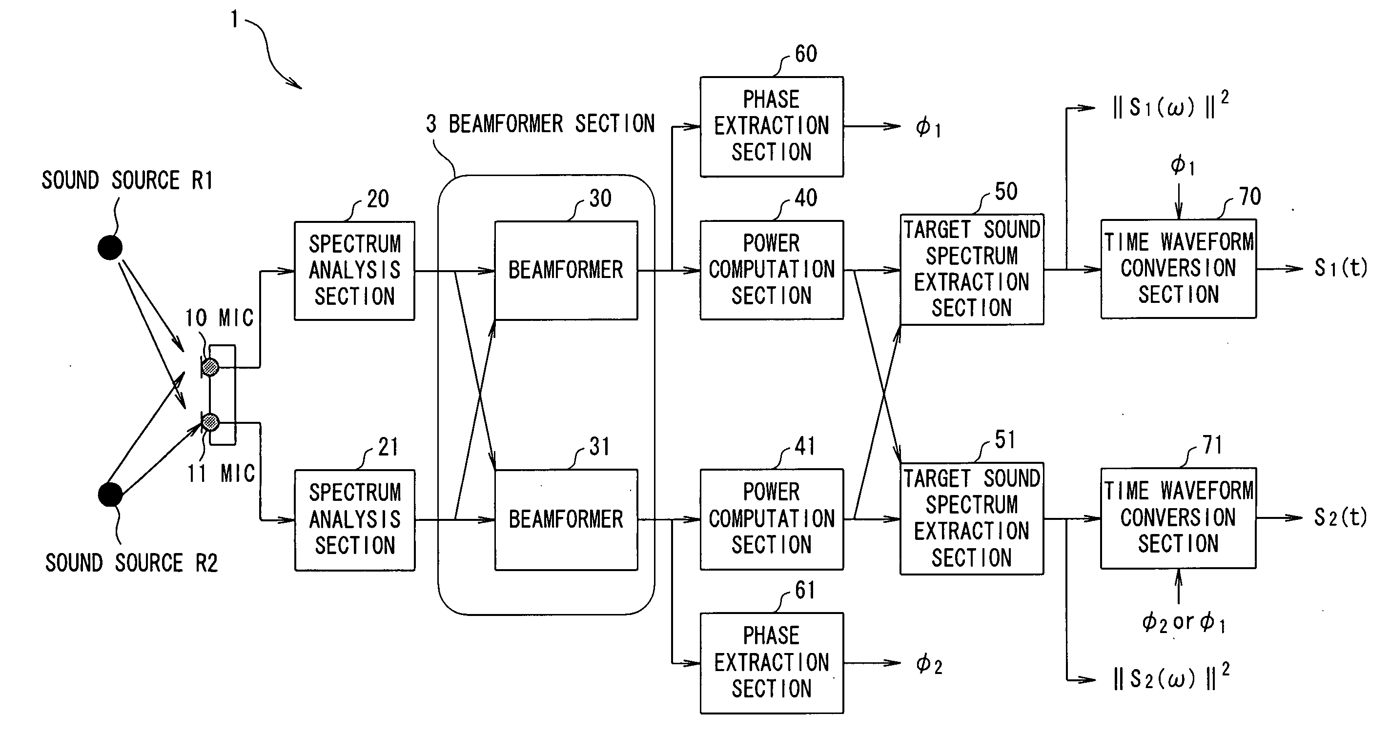
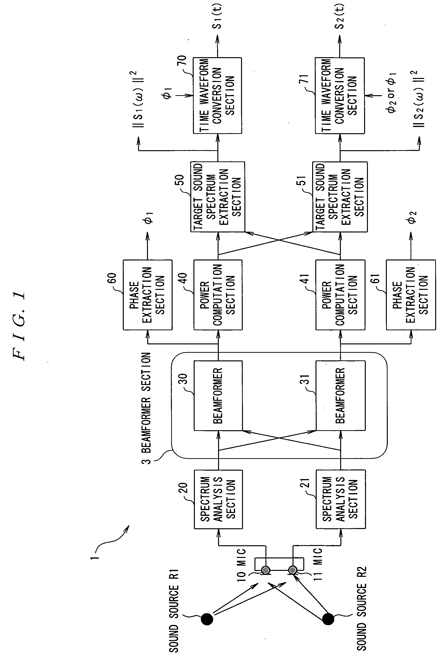
[0094]FIG. 1 is a diagram which shows a basic configuration of a sound source separation system according to the first embodiment of the present invention. This system is comprised of two microphones (hereinafter referred to as MIC) 10, 11 and a sound source separation device 1. This sound source separation device 1 includes a CPU that performs overall control and arithmetic processing, hardware including storage devices a ROM, a RAM, and a hard disk device, and software including a program, data, and the like stored in the storage devices, which are not shown. Function blocks shown in FIG. 1 are implemented by these hardware and software.

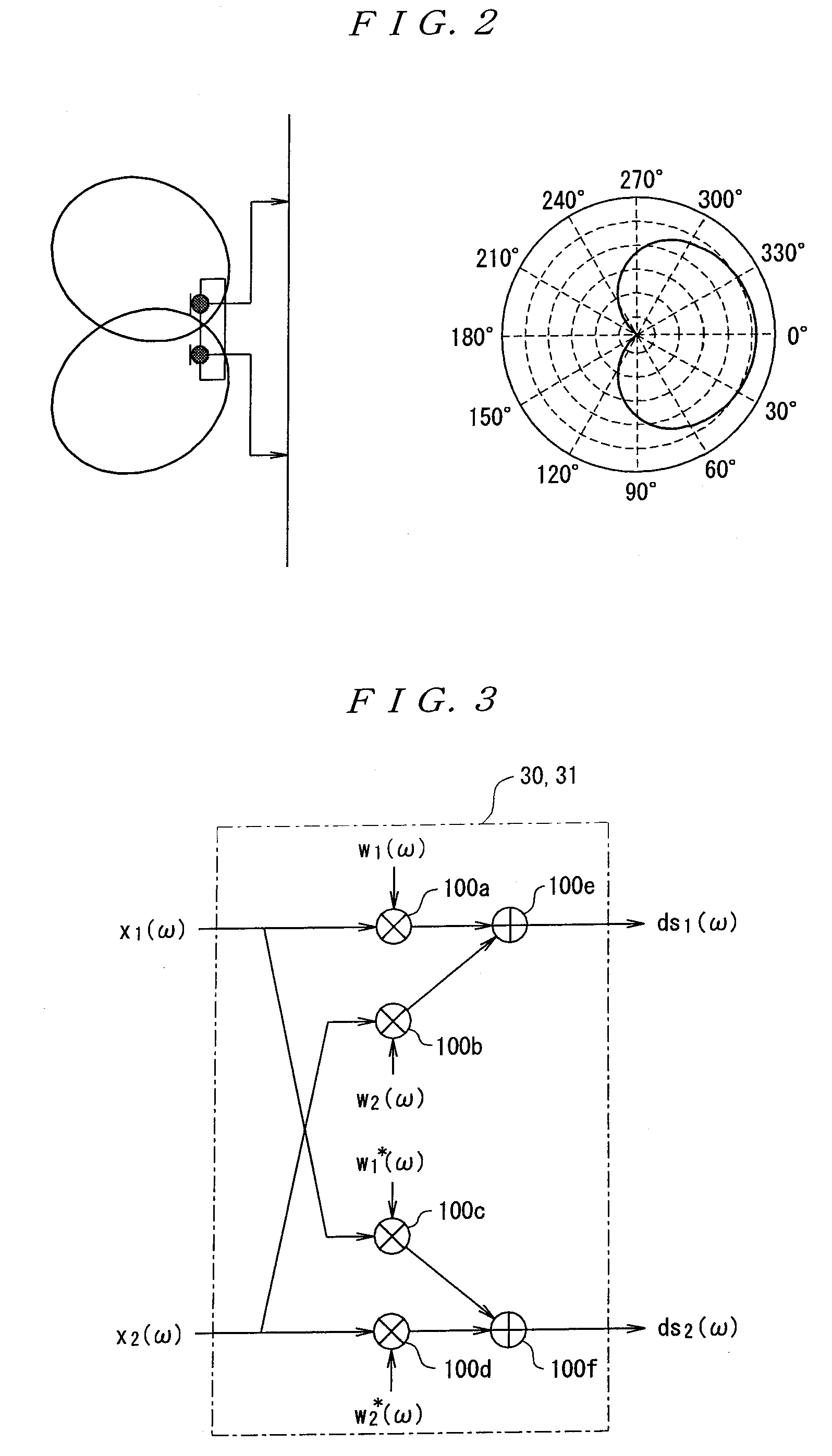
[0095]The two MICs 10 and 11 are non-directional MICs and arranged separately by a few centimeters from each other on a plane. Although the MICs 10 and 11 are basically omnidirectional, unidirectional microphones may be used as shown in FIG. 2. The MICs 10 and 11 receive signals emitted from two sound sources R1 and R2. At this time, these two soun...

second embodiment

[0130]Next, the second embodiment will be described. FIG. 17 shows a configuration of a sound source separation system according to the second embodiment. Although inputs from the MICs 10 and 11 are converted into frequency components at first by the spectrum analysis sections 20 and 21 in the above described first embodiment, in the present embodiment, a directional null is formed in a time domain by beamformers 80 and 81 at first, and generate a signal in which a signal from a specific arrival direction is attenuated by beamformers 80 and 81, and then conversion into frequency components is performed by the spectrum analysis sections 20 and 21. In FIG. 17, those having the same functions as in FIG. 1 are given the same reference numbers. Configurations of the beamformers 80 and 81 are implemented by performing filter processing configured as a form of an FIR filter or the like as shown in FIG. 18. At this time, coefficients of the FIR filter can be obtained by converting the weigh...

third embodiment

[0131]Next, the third embodiment will be described. FIG. 19 and FIG. 20 are diagrams which show configurations of sound source separation systems according to the third embodiment. As described above, the target sound spectrum extraction sections 50 and 51 shown in FIG. 1 and FIG. 17 are implemented as the configuration shown in FIG. 5, and are configured to perform sound source separation processing using an optimum threshold value obtained by experiment. On the other hand, as shown in FIG. 8, it is understood that dri(ω) (i=1, 2) which are outputs of the difference calculation sections 500 and 501 in the target sound spectrum extraction sections 50 and 51 are point-symmetric with respect to the front 0 degree. Therefore, when thresholds are set to “0” in the coefficient conversion sections 501 and 511 in the target sound spectrum extraction sections 50 and 51 by checking only signs in the calculation sections 500 and 501, if it is positive, power spectrum information of a sound so...


PUM


Abstract

A sound source signal from a target sound source is allowed to be separated from a mixed sound which consists of sound source signals emitted from a plurality of sound sources without being affected by uneven sensitivity of microphone elements. A beamformer section 3 of a source separation device 1 performs beamforming processing for attenuating sound source signals arriving from directions symmetrical with respect to a perpendicular line to a straight line connecting two microphones 10 and 11 respectively by multiplying output signals from the microphones 10 and 11 after spectrum analysis by weighted coefficients which are complex conjugate to each other. Power computation sections 40 and 41 compute power spectrum information, and target sound spectrum extraction sections 50 and 51 extract spectrum information of a target sound source based on a difference between the power spectrum information.

Description

TECHNICAL FIELD[0001]The present invention relates to a sound source separation device, a speech recognition device, a mobile telephone, a sound source separation method, and a program which uses a plurality of microphones and separates a sound source signal of a target sound source from a signal which consists of a plurality of acoustic signals emitted from a plurality of sound sources such as a plurality of speech signals and various background noises.BACKGROUND ART[0002]When a specific speech signal or the like is to be recorded under various environments, it is difficult to record only a signal of a target sound using a microphone since there are various noise sources in a peripheral environment, and therefore some sort of noise reduction processing or sound source separation processing is necessary.[0003]As an example where such processing is especially needed, there is an automotive environment. Under an automotive environment, due to the spread of mobile phones, a microphone ...

Claims


Application Information

Patent Timeline
IPC IPC(8): G10L21/02G10L15/20H04R3/00G10L15/06G10L15/28G10L21/0208G10L21/0232G10L21/0272G10L21/028G10L21/0308
CPCG10L15/20G10L21/0272G10L2021/02166H04R2499/13H04R2430/20H04R2499/11H04R1/406
Inventor NAGAHAMA, KATSUMASA
Owner ASAHI KASEI KK
Why Eureka
Try Eureka