Evanescent wave-coupled frequency selective surface

Inactive Publication Date: 2009-03-05
HARRIS CORP
View PDF4 Cites 48 Cited by
  • Summary
  • Abstract
  • Description
  • Claims
  • Application Information

AI Technical Summary

Benefits of technology

[0013]The invention also includes a method for exclusively passing two selected bands of RF energy through a multi-layer frequency selective panel. The method involves positioning a first frequency selective surface and a second frequency selective surface a predetermined distance apart in parallel planes. The method also includes selecting the predetermined distance so that the second frequency selective surface is disposed in an evanescent field region of the first frequency selective surface. A frequency of a first band and a frequency of a second band of the two selected bands of RF energy is selected by (1) choosing a geometry and size

Problems solved by technology

Still, it is known that the dielectric materials used for this purpose can create additional RF loss.
Further, these multiple layer arrangements tend to be relatively thic

Method used


Image

  • Evanescent wave-coupled frequency selective surface
  • Evanescent wave-coupled frequency selective surface
  • Evanescent wave-coupled frequency selective surface

Examples


Embodiment Construction

[0021]The invention will now be described more fully hereinafter with reference to accompanying drawings, in which illustrative embodiments of the invention are shown. This invention, may however, be embodied in many different forms and should not be construed as limited to the embodiments set forth herein.

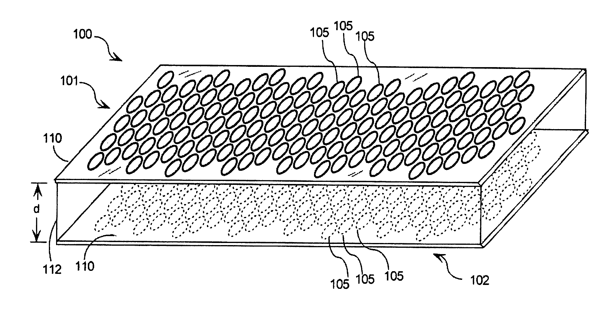
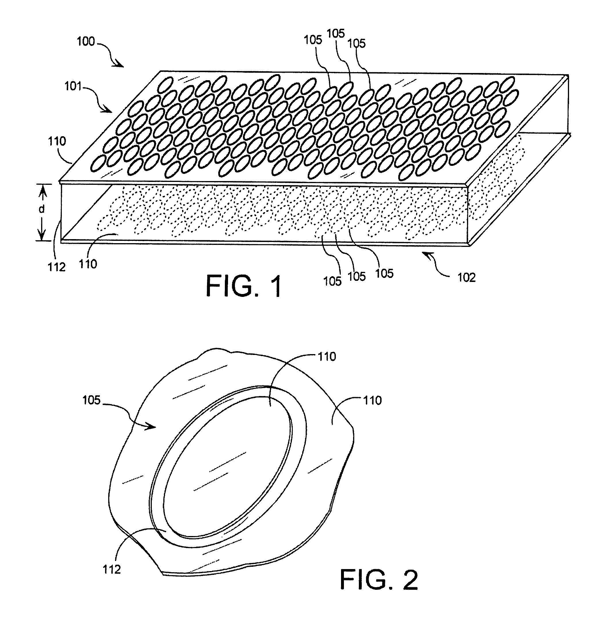
[0022]A multi-layer frequency selective panel (MLFSP) 100 is shown in FIG. 1. The MLFSP 100 is formed from a plurality of frequency selective surfaces (FSS) arranged as a plurality of layers in a stack formation. In the embodiment shown in FIG. 1, the MLFSP 100 includes a first FSS 101 comprising a first plurality of elements 105, and a second FSS 102 comprising a second plurality of elements 105. The first FSS 101 and the second FSS 102 are positioned a predetermined distance apart which is identified in FIG. 1 by the letter d. Further, as can be observed in FIG. 1, the first and second FSS 101, 102 are oriented in parallel planes so as to form layers of the MLFSP 100.

[0023]The f...


PUM


Abstract

Multi-layer frequency selective panel includes a group of frequency selective surfaces arranged in a stack. A first frequency selective surface includes a first group of slot elements, and a second frequency selective surface includes a second group of slot elements. The first frequency selective surface and the second frequency selective surface are formed of a conductive metal layer. The first frequency selective surface and the second frequency selective surface are positioned a predetermined distance apart in parallel planes. The second frequency selective surface is disposed in an evanescent field region of the first frequency selective surface.

Description

BACKGROUND OF THE INVENTION[0001]1. Statement of the Technical Field[0002]The inventive arrangements concern frequency selective surfaces, and more particularly frequency selective surfaces having improved performance, reduced thickness, and reduced weight.[0003]2. Description of the Related Art[0004]A frequency selective surface (FSS) is conventionally designed to either block or pass electromagnetic waves at a selected frequency or frequencies. These types of surfaces are essentially periodic resonance structures that are comprised of a conducting sheet periodically perforated with closely spaced apertures. Alternatively, these structures may be comprised of an array of periodic metallic patches. Many types of FSS element configurations are known, including tripoles, circular rings, Jerusalem crosses, concentric rings, mesh-patch arrays or double squares supported by a dielectric substrate. Depending upon the geometry selected, these can combine features of inductive and capacitiv...

Claims


Application Information

Patent Timeline
IPC IPC(8): H01Q13/10H01Q9/04
CPCH01Q15/0013H01Q15/0026
Inventor DELGADO, HERIBERTO J.AHRENDT, MITCHELL
Owner HARRIS CORP
Why Eureka
Try Eureka